
LED lamp with 360-degree illumination

a technology of led lamps and lampshades, applied in the field of led lamps, can solve the problems of increasing production costs and assembly time, increasing maintenance time and cost, and still having some structural problems

Inactive Publication Date: 2011-11-01
EDISON-OPTO
View PDF3 Cites 25 Cited by
  • Summary
  • Abstract
  • Description
  • Claims
  • Application Information

AI Technical Summary

Benefits of technology

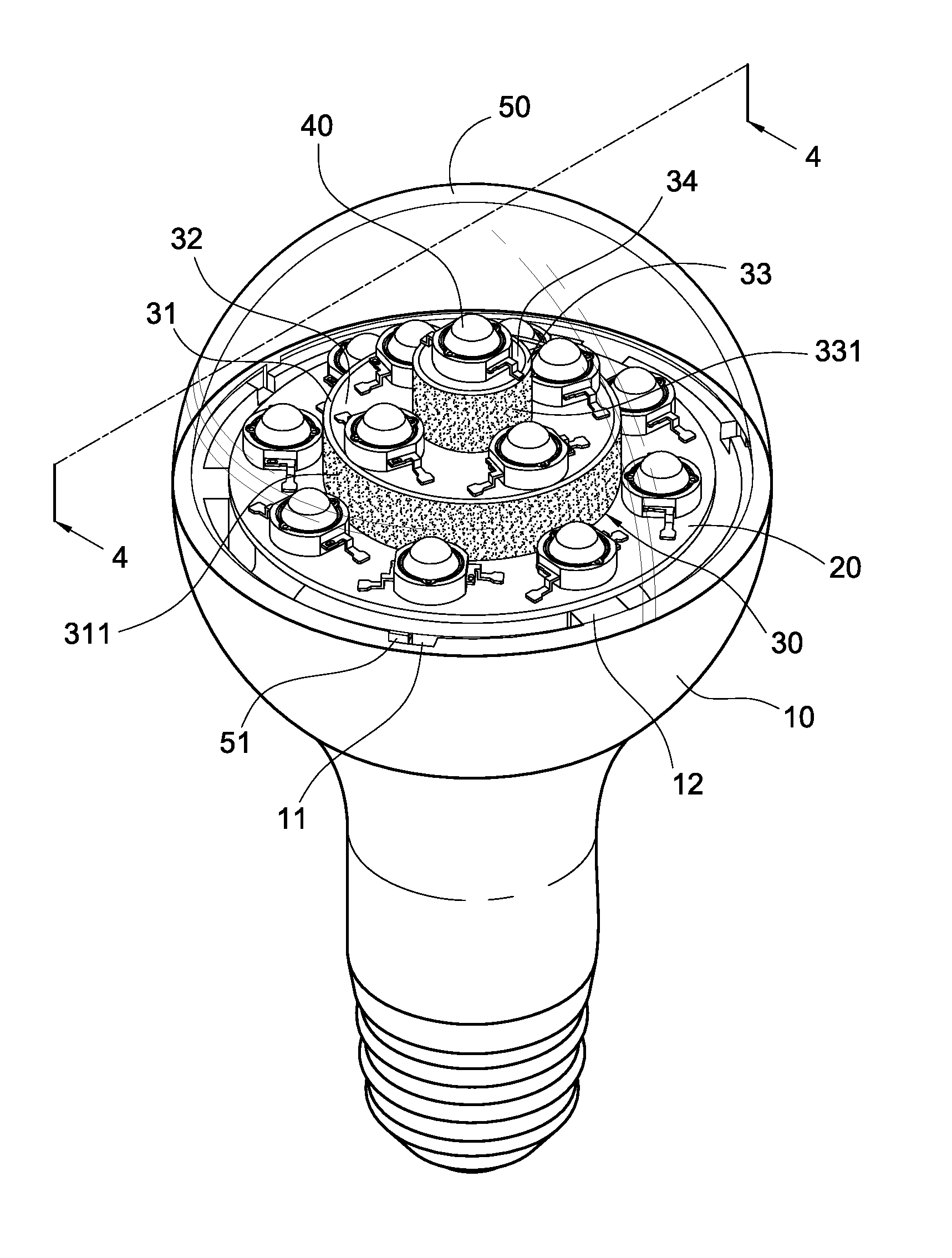
"The present invention is a LED lamp with 360-degree illumination. It includes a base, a first substrate, a stepped structure, and a plurality of LEDs. The stepped structure has a first annular frame, a second substrate, and a second annular frame. The LEDs are fixed on the first and second substrates and surround the first and second annular frames, respectively. The LEDs are distributed less densely on the stepped surface, which allows for better thermal conduction and heat dissipation. The reflective layers on the external surfaces of the annular frames reflect the lights emitted by the LEDs, increasing the brightness in the lateral direction of the lamp. The present invention can use a smaller number of LEDs, reducing production cost and assembly time."

Problems solved by technology

However, in practice, such a structure still has some problems as follows.
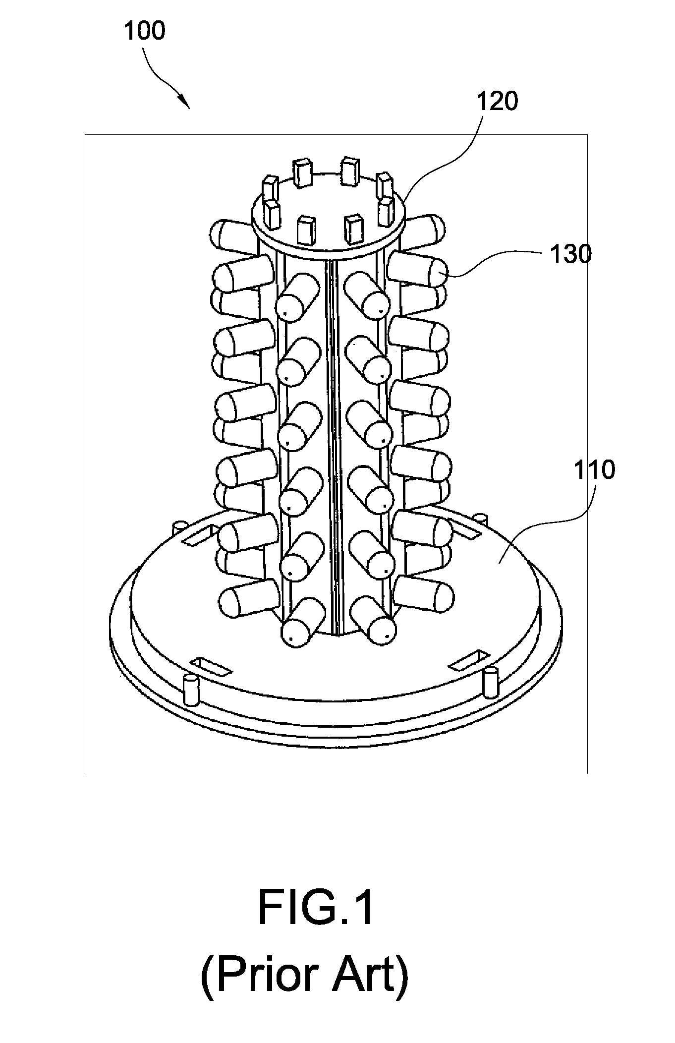
In order to achieve the required 360-degree illumination and brightness, it is necessary to increase the number of LEDs 130, which also increases the production cost and time for assembly.
As a result, the working temperature of the LEDs 130 is so high that the life of the LEDs 130 will be deteriorated, which may increase the time and cost for maintenance.

Method used


Image

  • LED lamp with 360-degree illumination
  • LED lamp with 360-degree illumination
  • LED lamp with 360-degree illumination

Examples


Embodiment Construction

[0019]The characteristics and technical contents of the present invention will be described with reference to the accompanying drawings. However, the drawings are illustrative only but not used to limit the present invention.

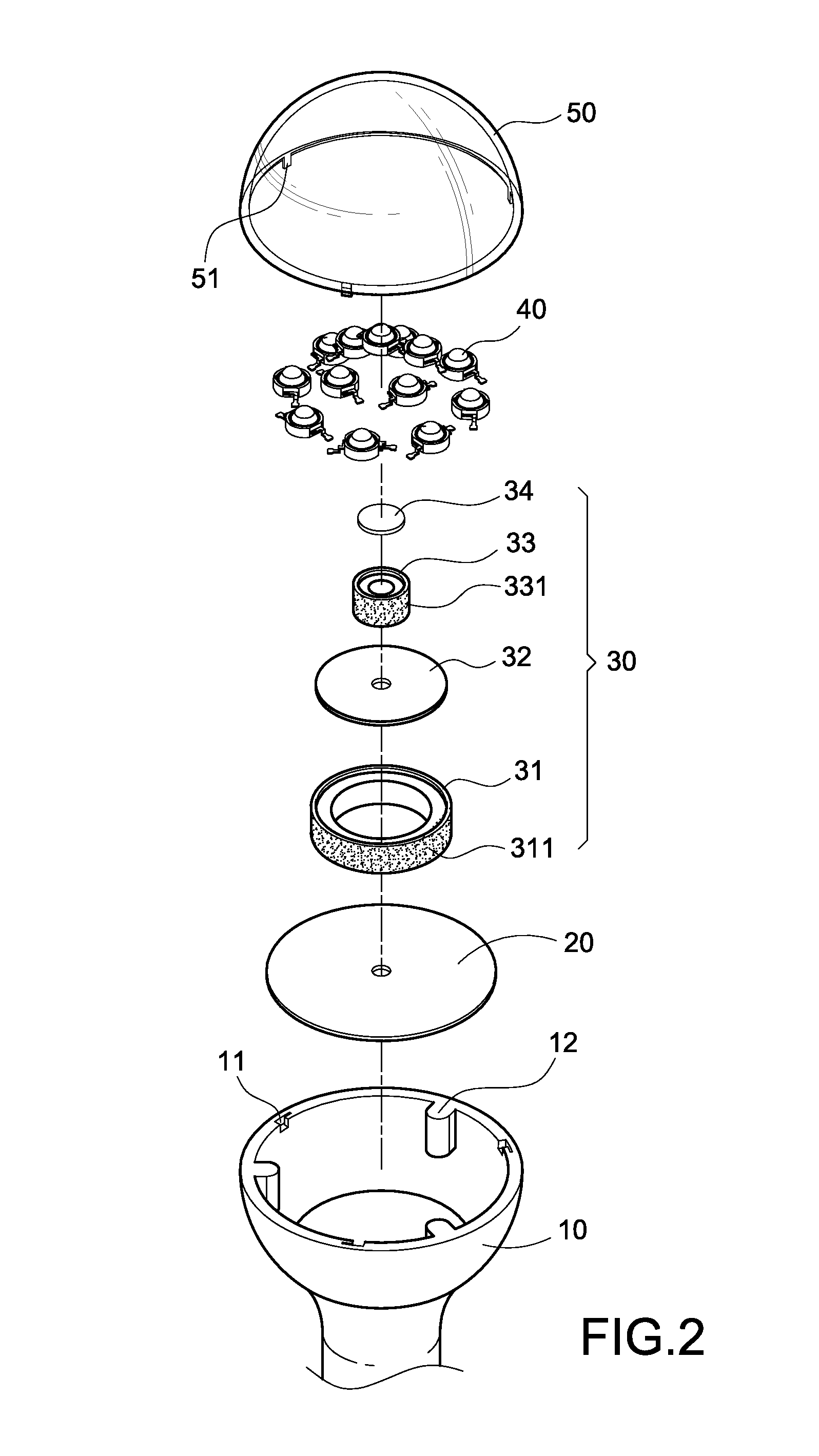
[0020]Please refer to FIG. 2, which is an exploded perspective view of the present invention. The present invention provides a LED lamp with 360-degree illumination, which includes a base 10, a first substrate 20, a stepped structure 30, a plurality of LEDs 40, and a cover 50. Further, a heat sink 60 (not shown in FIG. 2, please refer to FIG. 5) is attached to one surface of the first substrate 20 opposite to the LEDs 40. The heat sink 60 is used to dissipate the heat generated by the whole LED lamp, which will be described later in more detail.

[0021]In one embodiment of the present invention, an upper portion of the base 10 and the cover 50 together form a hollow semi-spherical body. The edge of the cover 50 is provided with a plurality of hooks 51. The edge of...


PUM


Abstract

A LED lamp with 360-degree illumination includes a base, a first substrate, a stepped structure, a plurality of LEDs, and a cover. The first substrate is fixed on the base. The stepped structure is mounted on the first substrate. The stepped structure has a first annular frame connected to the first substrate, a second substrate connected to the first annular frame, and a second annular frame connected to the second substrate. The peripheral length of the second annular frame is smaller than that of the first annular frame. The plurality of LEDs is fixed to the first substrate and the second substrate and surrounds the first annular frame and the second annular frame respectively. With this arrangement, the LEDs can be arranged in a multi-storey stepped structure to generate an effect of 360-degree illumination. Also, the illumination range of the lamp can be increased.

Description

BACKGROUND OF THE INVENTION[0001]1. Field of the Invention[0002]The present invention relates to a LED lamp, and in particular to a LED lamp with 360-degree illumination.[0003]2. Description of Prior Art[0004]Since light emitting diodes (LEDs) have advantages of low electricity consumption, environmental protection, long life, small volume and toughness, they have been widely used in various fields such as automobiles, communication industries or consumptive electronic appliances to replace traditional light sources. However, the lights emitted by the LEDs are concentrated in a certain range. Thus, manufacturers in this industry continue to develop a lamp with 360-degree illumination. For example, Taiwan Patent Publication No. M306299 discloses a lamp 100 with 360-degree illumination. As shown in FIG. 1, the center of a base 110 is provided with a post 120. The outer surface of the post 120 is provided with a plurality of LEDs 130 arranged in vertical lines, whereby the 360-degree i...

Claims


Application Information

Patent Timeline
Patent Type & Authority Patents(United States)
IPC IPC(8): F21V21/00
CPCF21K9/00F21K9/135F21V3/00F21V7/0058F21V7/043F21V19/003F21Y2111/008F21Y2103/022F21Y2111/001F21Y2105/005F21Y2101/02F21K9/232F21Y2103/33F21Y2107/00F21Y2107/50F21Y2107/60F21Y2115/10
Inventor WU, CHIEN-JUNGSUN, TSUNG-TING
Owner EDISON-OPTO
Learn More