In-vehicle display device

a display device and vehicle technology, applied in the direction of static indicating devices, identification means, instruments, etc., can solve the problems of inability to accommodate projectors inside the instrument panel, inability to achieve the interior design of the automobile and the appearance of the cockpit, and the increase of the manufacturing cost of the hud device as a whole, so as to improve the visibility of the driver during driving.

Inactive Publication Date: 2011-11-01
YAZAKI CORP
View PDF11 Cites 26 Cited by
  • Summary
  • Abstract
  • Description
  • Claims
  • Application Information

AI Technical Summary

Benefits of technology

[0012]In view of the above-identified drawbacks, the present invention is to provide an in-vehicle display device that can be readily provided on an instrument panel of an automobile with a reduced manufacturing cost.
[0015]Also, in contrast to conventional head-up display devices, the display unit can be integrally or separately provided on the surface of the instrument panel, and the display device does not need to be mounted with high accuracy and the instrument panel does not need to have a space dedicated to installation of the display device. Also, since only the necessary information dots are selectably indicated on the windshield, a distance between the display unit and the windshield can be reduced, an expensive reflection member does not need to be provided, and the display unit can directly project virtual images (the information dots) on the windshield. Also, even when the virtual images are indicated over a wide range of the windshield, degradation of driver's visibility can be avoided.
[0016]Further, by indicating the desired information dot or dots, the driver's attention and viewpoint can be directed toward the target information, and, at the same time, the driver can in an intuitive manner recognize the information dot or dots. Accordingly, the display device can be readily mounted on the instrument panel of the vehicle with reduced manufacturing cost.
[0019]Also, the information dots can be associated with a real image existing in the vehicle's traveling direction or the information dots can be superposed on the real image viewed through the windshield. Consequently, the driver's consciousness and viewpoint can be moved within the wide range on the windshield and the driver's driving can be effectively supported.
[0022]Since the information dot or dots that have been selected can be associated with or superposed on the real image of the detected obstacle and the information dot or dots are indicated on the windshield, the driver's attention and viewpoint can be moved toward the target obstacle by means of the presentation of the information dots and driver's safety driving can be effectively supported.
[0025]Since it can be selected whether or not the information dot or dots are indicated in the display area, the information dots can be flexibly indicated depending upon the driver's preference and needs. Also, by making the display area or an area other than that correspond to the driver's range of vision is not interrupted by the information dots, so that the driver's visibility during driving can be improved.

Problems solved by technology

Accordingly, the HUD device has to incorporate expensive reflection members that cause a manufacturing cost of the HUD device as a whole to increase.
Further, when the virtual images are to be projected using the conventional HUD device over a wide area of the windshield, as disclosed for example in the 2003-291688 document, a projector cannot be accommodated inside of the instrument panel, which is undesirable in terms of interior design of the automobile and appearance of a cockpit.
Also, a size of the conventional virtual image and its display position on the windshield is limited so as not to interrupt a driver's range of vision while driving, and it is difficult for the driver to instantaneously recognize the virtual image while driving.
Further, the drive support system with night-vision capability only allows a limited display area with a number of still and / or moving images to a detriment of driver's visibility.

Method used


Image

  • In-vehicle display device
  • In-vehicle display device
  • In-vehicle display device

Examples


Embodiment Construction

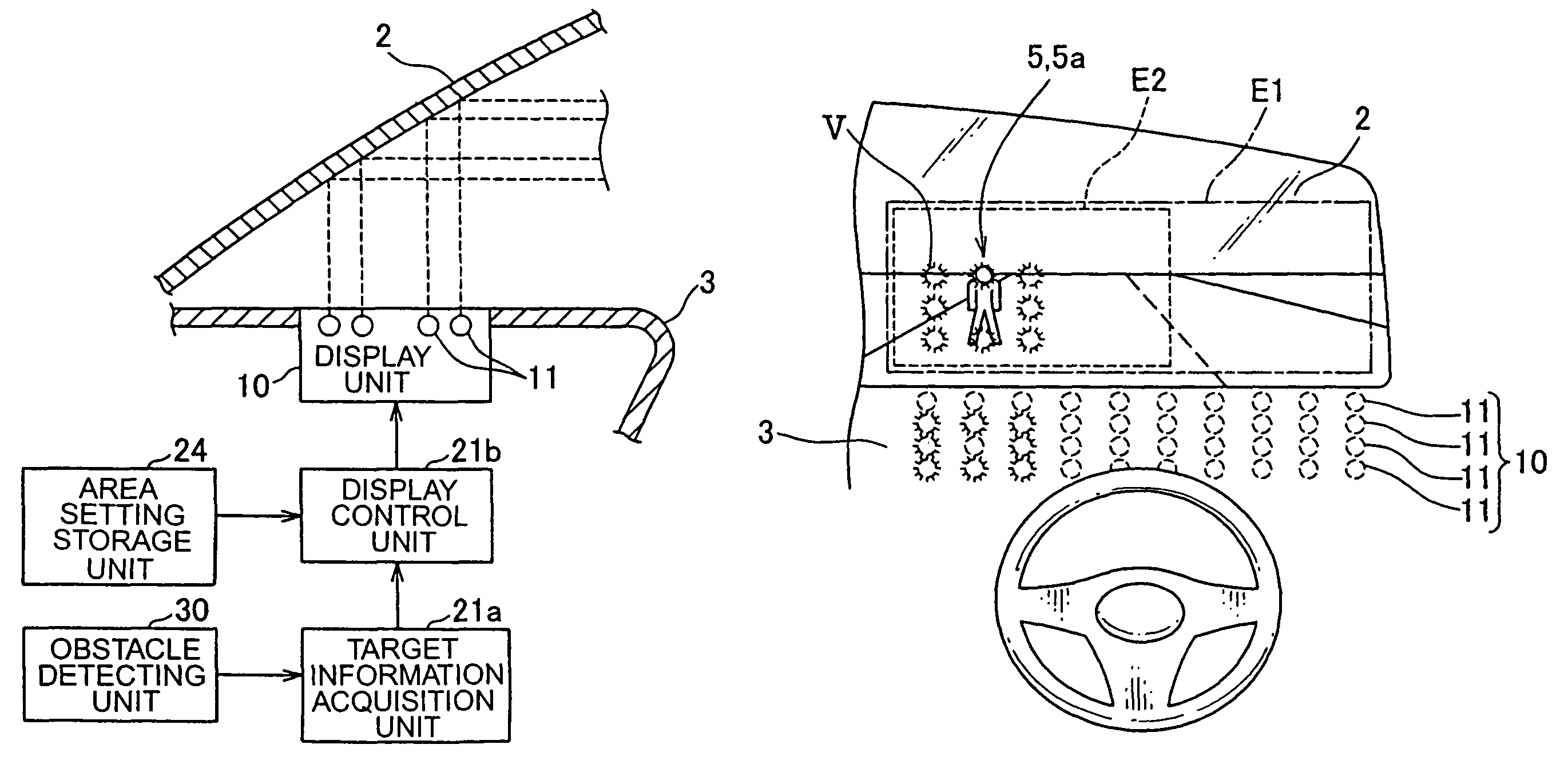
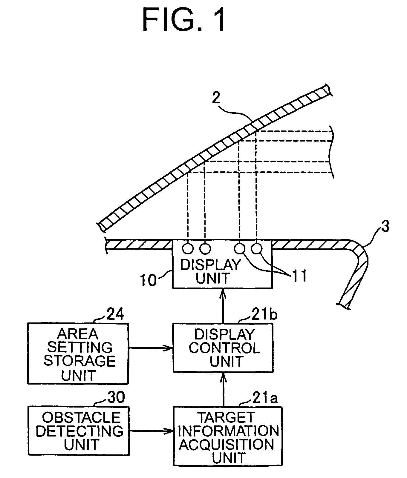
[0039]Basic configuration of an in-vehicle display device that the present invention envisages is illustrated in FIG. 1.

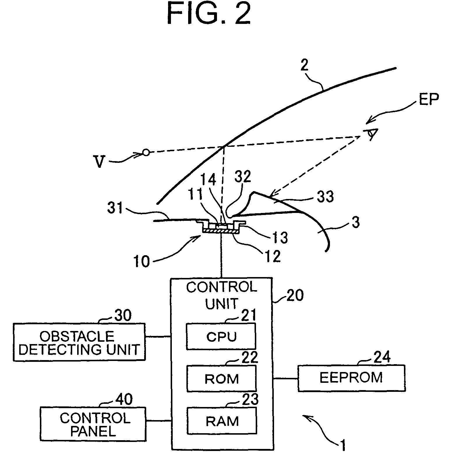
[0040]An in-vehicle display device according to one embodiment of the present invention is described below with reference to FIGS. 2 to 9.

[0041]Referring to FIG. 2, the in-vehicle display device 1 has a display unit 10, a control unit 20, an obstacle detecting unit 30, and a control panel 40. The display unit 10, the obstacle detecting unit 30, and the control panel 40 are electrically connected to the control unit 20 via known interfaces (not shown).

[0042]The display unit 10 is provided on a surface 31 of an instrument panel 3 such that the display unit 10 is opposed to a windshield 2 of a vehicle. Referring to FIG. 3, the display unit 10 has a plurality of point light sources 11 (for example, an LED or a bulb). The point light sources 11 are provided on the instrument panel 3 and are arranged in a width direction of a vehicle body such that a plurality of informa...


PUM


Abstract

An in-vehicle display device includes (a) a display unit provided on a surface of an instrument panel of a vehicle, opposed to a windshield of the vehicle, and configured to indicate a plurality of information dots V in a row or in a rectangular array on the windshield such that the necessary information dots are selectably displayed from among the plurality of the information dots and superposed upon a real image viewed through the windshield, (b) a target information acquisition unit that obtains target information of which a driver of the vehicle is to be notified, and (c) a display control unit that controls the display unit and makes the display unit indicate the predetermined information dots V that correspond to the target information that has been obtained by the target information acquisition unit.

Description

CROSS REFERENCE TO RELATED APPLICATION[0001]The priority application Japanese Patent Application No. 2008-062405 upon which the present patent application is based is hereby incorporated by reference.BACKGROUND OF THE INVENTION[0002]1. Field of the Invention[0003]The present invention generally relates to an in-vehicle display device, and more specifically to an in-vehicle display device that includes a display unit provided on a surface of an instrument panel of an automobile and configured to indicate one or more information dots on a windshield of the automobile.[0004]2. Background of the Related Art[0005]Recently, increasing number of various vehicles embrace a display device that incorporates techniques of projecting information directly into a human's field of vision, i.e., a head-up display (HUD) device. The display device of this kind helps improving driver's visibility. A virtual image presented by the display device is superposed on the landscape that can be seen ahead of ...

Claims


Application Information

Patent Timeline
Patent Type & Authority Patents(United States)
IPC IPC(8): B60Q1/00G03B21/56G06K9/00G09G5/00
CPCB60K35/00G02B27/01G02B2027/0127G02B2027/0138B60Q3/78B60K2370/191B60K2370/194B60K2370/338B60K2370/785B60Q9/00
Inventor TAKAHASHI, NOBUYUKIAOKI, KUNIMITSUTAKAMATSU, MASAHIRO
Owner YAZAKI CORP
Why Eureka
Try Eureka