
Determination of diesel particulate filter load under both transient and steady state drive cycles

a technology of diesel particulate filter and steady-state drive cycle, which is applied in the direction of engines, mechanical equipment, machines/engines, etc., can solve the problems of reducing fuel economy, affecting the operation life of pf regeneration, and degrading pf ceramics

Active Publication Date: 2011-11-08
FORD GLOBAL TECH LLC
View PDF15 Cites 25 Cited by
  • Summary
  • Abstract
  • Description
  • Claims
  • Application Information

AI Technical Summary

Benefits of technology

[0002]A particulate filter (PF) may be used to reduce particulate matter emissions in engines, such as diesel engines. The PF may be periodically regenerated to remove accumulated particulate matter. The regeneration may be achieved by raising the temperature of the PF to a predetermined level to oxidize the accumulated particulate matter.
[0003]Timing of the PF regeneration may affect the operational life of the PF since regeneration of a PF overloaded with particulate matter may generate overly high temperatures and potentially degrade the PF ceramics due to overheating. On the other hand, too frequent regeneration may result in reduced fuel economy, as energy is used to raise the exhaust temperature. Further, too frequent regeneration may result dilution of engine lubricating oil, thereby causing increased warranty due to higher component wear.
[0006]To at least partially address the above mentioned issues, the inventors herein provide various systems and methods for updating the PF soot load of an engine. In one embodiment, the method may include performing regeneration in response to both pressure-based measurements as well as estimated soot loading independent of the pressure-based measurements, where during conditions in which the pressure-based measurements may be inaccurate, the soot load is estimated based on operating conditions and previous pressure-based measurements that occurred during previous conditions in which the pressure-based measurements are more accurate. In this way, more continuous monitoring of particulate filter loading is provided, while taking advantage of pressure-based measurements from the most recent accurate reading, for example, and operating conditions that have transpired since such reading, including transient conditions. Thus, more appropriately timed regeneration may be provided.

Problems solved by technology

Timing of the PF regeneration may affect the operational life of the PF since regeneration of a PF overloaded with particulate matter may generate overly high temperatures and potentially degrade the PF ceramics due to overheating.
On the other hand, too frequent regeneration may result in reduced fuel economy, as energy is used to raise the exhaust temperature.
Further, too frequent regeneration may result dilution of engine lubricating oil, thereby causing increased warranty due to higher component wear.
In particular, pressure-based measurements may be too inaccurate at low exhaust volume flows due to degraded accuracy of sensors at the limits of their operating range.
In addition, pressure-based measurements may be too inaccurate during transient conditions due to high time constants of the sensors and unsteady fluid dynamics in the exhaust system.

Method used


Image

  • Determination of diesel particulate filter load under both transient and steady state drive cycles
  • Determination of diesel particulate filter load under both transient and steady state drive cycles
  • Determination of diesel particulate filter load under both transient and steady state drive cycles

Examples


Embodiment Construction

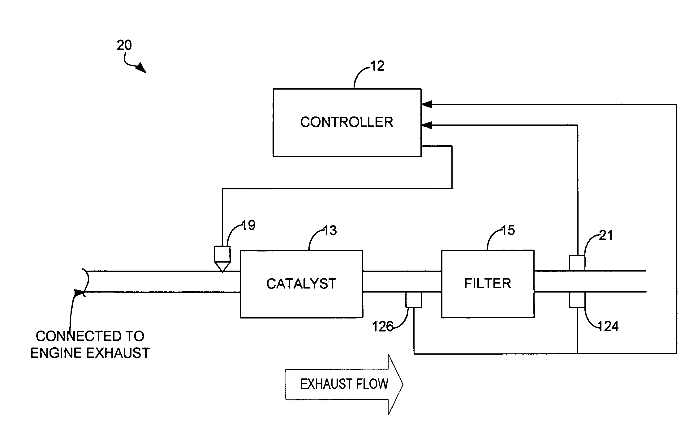
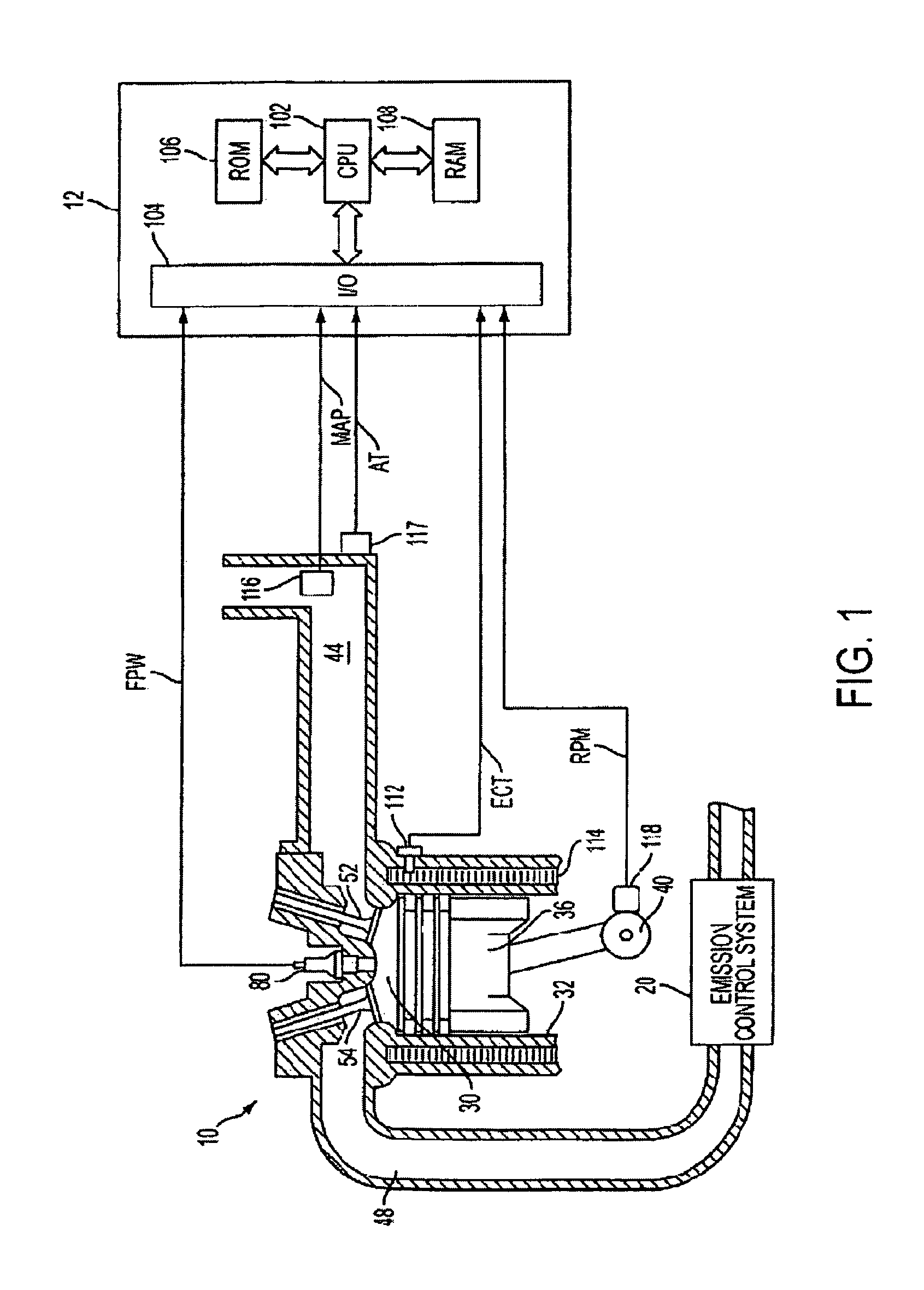
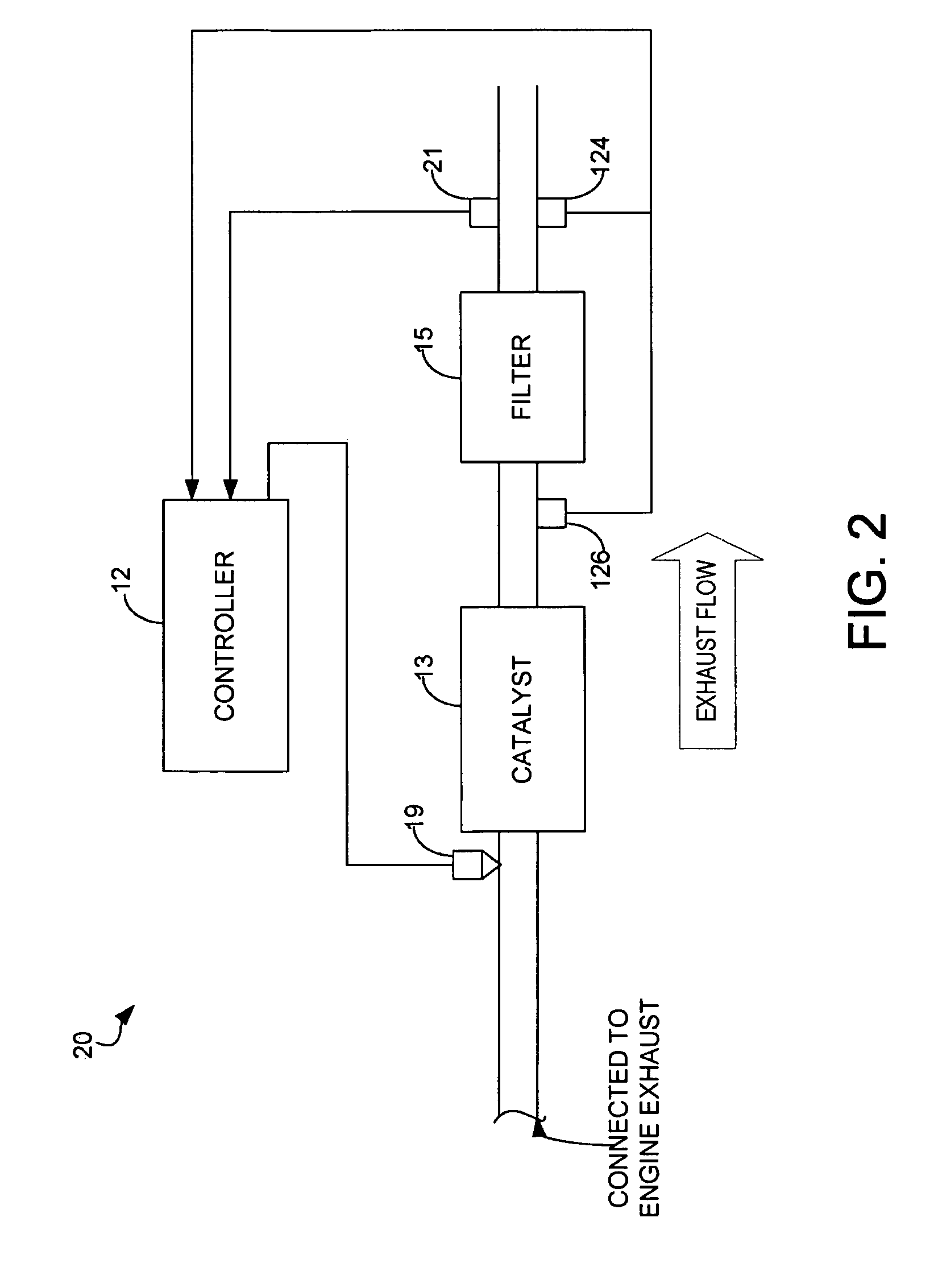
[0011]FIG. 1 is a schematic diagram of an example internal combustion engine 10 in which the disclosed system and method for monitoring soot load of a particulate filter may be implemented. The engine may be a diesel engine in one example.

[0012]Internal combustion engine 10, comprising a plurality of cylinders, one cylinder of which is shown in FIG. 1, is controlled by electronic engine controller 12. Engine 10 includes combustion chamber 30 and cylinder walls 32 with piston 36 positioned therein and connected to crankshaft 40. Combustion chamber 30 is shown communicating with intake manifold 44 and exhaust manifold 48 via respective intake valve 52 and exhaust valve 54. Engine 10 is shown as a direct injection engine with injector 80 located to inject fuel directly into cylinder 30. Fuel is delivered to fuel injector 80 by a fuel system (not shown), including a fuel tank, fuel pump, and high pressure common rail system. Fuel injector 80 delivers fuel in proportion to the pulse widt...


PUM


Abstract

Methods for updating the PF soot load of an engine are provided herein. In one example, a soot storage estimate is based on processing operations that occur at different timings. The method can improve soot estimation during some conditions.

Description

[0001]The present application claims priority to U.S. Provisional Patent Application No. 61 / 014,721, filed Dec. 18, 2007, titled “Determination of Diesel Particulate Filter Load Under Both Transient and Steady State Drive Cycles,” the entire contents of each of which are incorporated herein by reference.BACKGROUND AND SUMMARY[0002]A particulate filter (PF) may be used to reduce particulate matter emissions in engines, such as diesel engines. The PF may be periodically regenerated to remove accumulated particulate matter. The regeneration may be achieved by raising the temperature of the PF to a predetermined level to oxidize the accumulated particulate matter.[0003]Timing of the PF regeneration may affect the operational life of the PF since regeneration of a PF overloaded with particulate matter may generate overly high temperatures and potentially degrade the PF ceramics due to overheating. On the other hand, too frequent regeneration may result in reduced fuel economy, as energy ...

Claims


Application Information

Patent Timeline
Patent Type & Authority Patents(United States)
IPC IPC(8): F01N3/00
CPCF01N9/002Y02T10/47Y02T10/40
Inventor CHAMARTHI, GOPAL K.KRENZ, EDWIN ALLENWASKIEWICZ, DAVID CHESTERLYON, PETER MITCHELLGRESENS, BRADLEY D.OPOLSKY, NORMAN HIAMVAN NIEUWSTADT, MICHIEL J.
Owner FORD GLOBAL TECH LLC
Learn More