Swinging chute linkage assembly

a technology of concrete chute and linkage assembly, which is applied in the direction of seed depositing seeder parts, emergency apparatus, aircraft ejection means, etc., can solve the problems of large stress on the chute joint and actuator assembly, inefficient delivery of functional forces from the actuator system, and failure to meet the requirements of the industry. , to achieve the effect of reducing wear and tear, increasing the efficiency of actuation energy, and increasing the strength of the join

Active Publication Date: 2011-11-08
LMI US LLC
View PDF12 Cites 8 Cited by
  • Summary
  • Abstract
  • Description
  • Claims
  • Application Information

AI Technical Summary

Benefits of technology

[0009]The current advance provides a folding delivery chute joint structure for concrete mixers that increases the strength of the joint and increases the efficient delivery of actuation energy through the joint, which in turn results in a component with reduced wear, lower maintenance costs, and less unpredictable maintenance down time.
[0010]The hinge structure prevents tangential rotation about the joint pivot pins, thereby enabling transfer of operational energy more efficiently and effectively to deploy or retract the concrete delivery chute segments.
[0011]The current invention applies multiple forked or clevis elements to create a balanced, stronger joint that resists torsional or twisting aspects and overcomes deficiencies of designs currently used in the art. A resulting multi-pronged design of the current linkage configuration provides a plurality of spaced pivot attachment points on opposing sides of connecting linkage components. This three-pronged design supports the attendant joints along the entire pivot axis in the deployment / retraction linkage system. The uniform support of the three-pronged arcuate design, derived from the extended support at these pivotal axis points, counteracts the torsional forces that have the tendency to induce an undesired rotation that is generally perpendicular to the direction of the desired hinge rotation.
[0012]In addition, the three pronged design increases the number of contact points about the pivotal axis, which in turn increases the strength of the pivotal joint because the additional contact points provide greater stability and control of the pivot bolt or pin. The rotational resistive forces are deployed on either side of the rotation pivot point created by traditional designs and thereby prevent the pivot pin from undergoing perpendicular rotation about the axis point.

Problems solved by technology

It is well known in the art that folding chute sections utilized for the discharge and delivery of concrete from the mixing drum are typically heavy and produce large stresses on the chute joints and actuator assemblies, particularly when loaded with concrete.
The operation actuator and hinge assemblies experience significant resistive and torsional forces that result in rapid damaging wear and tear upon the parts.
Additionally, designs commonly employed within the industry, while successful, are inefficient as to the delivery of functional forces from the actuator system to the point of deployment because of limitations in the hinge mechanisms.
One common limitation with existing single eyelet hinge configurations occurs because a strong twisting force and motion results when the actuator operates as the actuator force is delivered through the joint to deploy or retract the chute segment.
The twisting forces place unwanted stress on the hinge components resulting in undue wear and tear on the components.
This wear and tear on the chute joints results in excessive maintenance costs and inconvenient down time to repair the vehicle.

Method used


Image

  • Swinging chute linkage assembly
  • Swinging chute linkage assembly
  • Swinging chute linkage assembly

Examples


Embodiment Construction

[0021]Embodiments of the present invention are described herein with reference to FIGS. 1 through 3. The principles, the illustrative embodiments, and modes of operation for the present invention are described in the following specification. However, the invention, which is intended to be protected, is not to be construed as limited to the particular embodiment disclosed. Further, the embodiments described herein are meant to be regarded as illustrative rather than restrictive. Variations and changes may be made by others skilled in the art, and equivalents employed, without departing from the spirit of the present invention. Accordingly, it is expressly intended that all such variations, changes, and equivalents that fall within the spirit and scope of the present invention as defined in the claims, be embraced thereby.

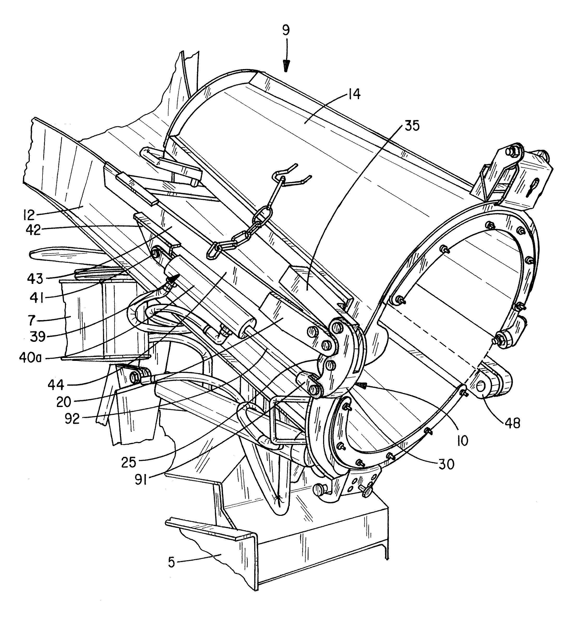
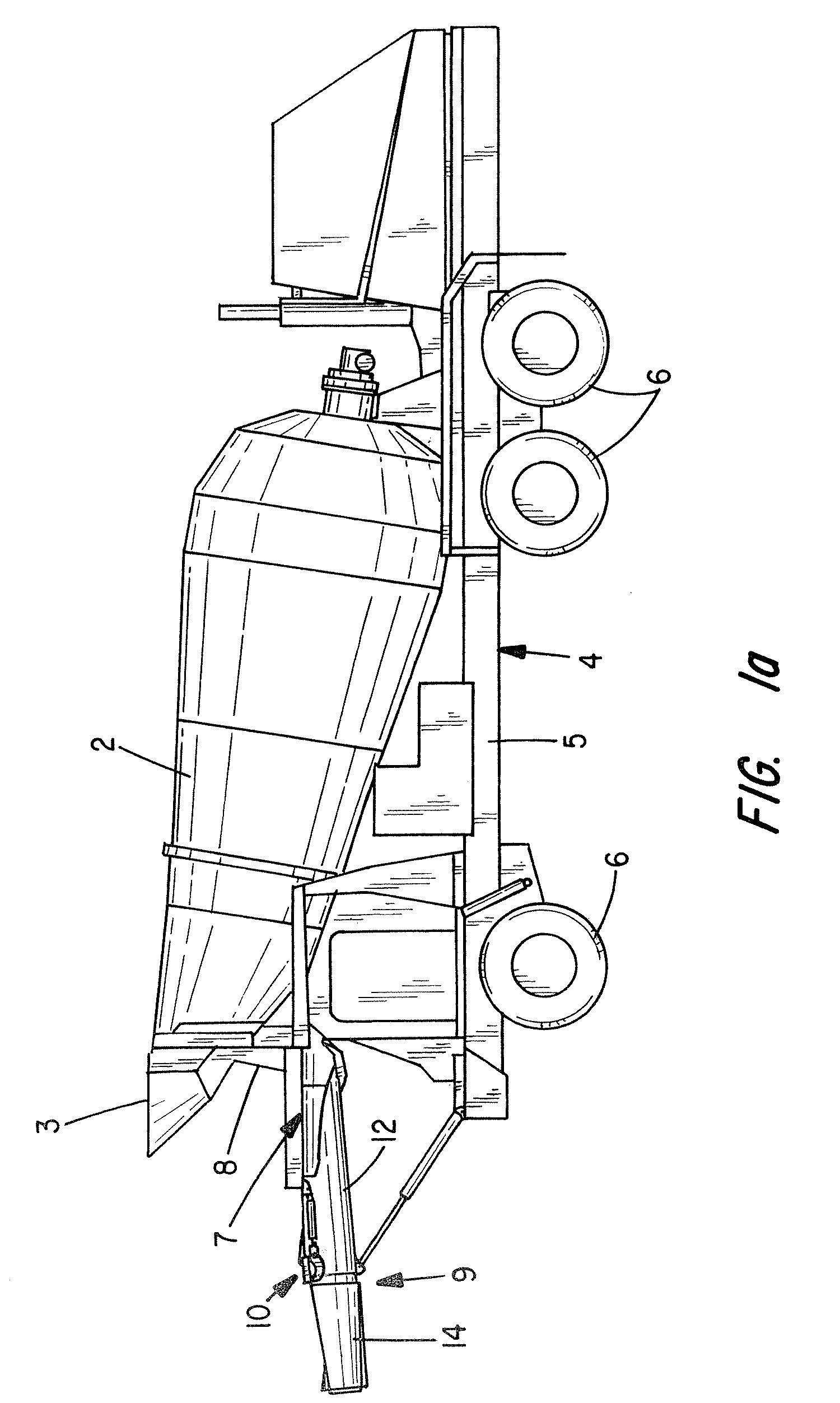
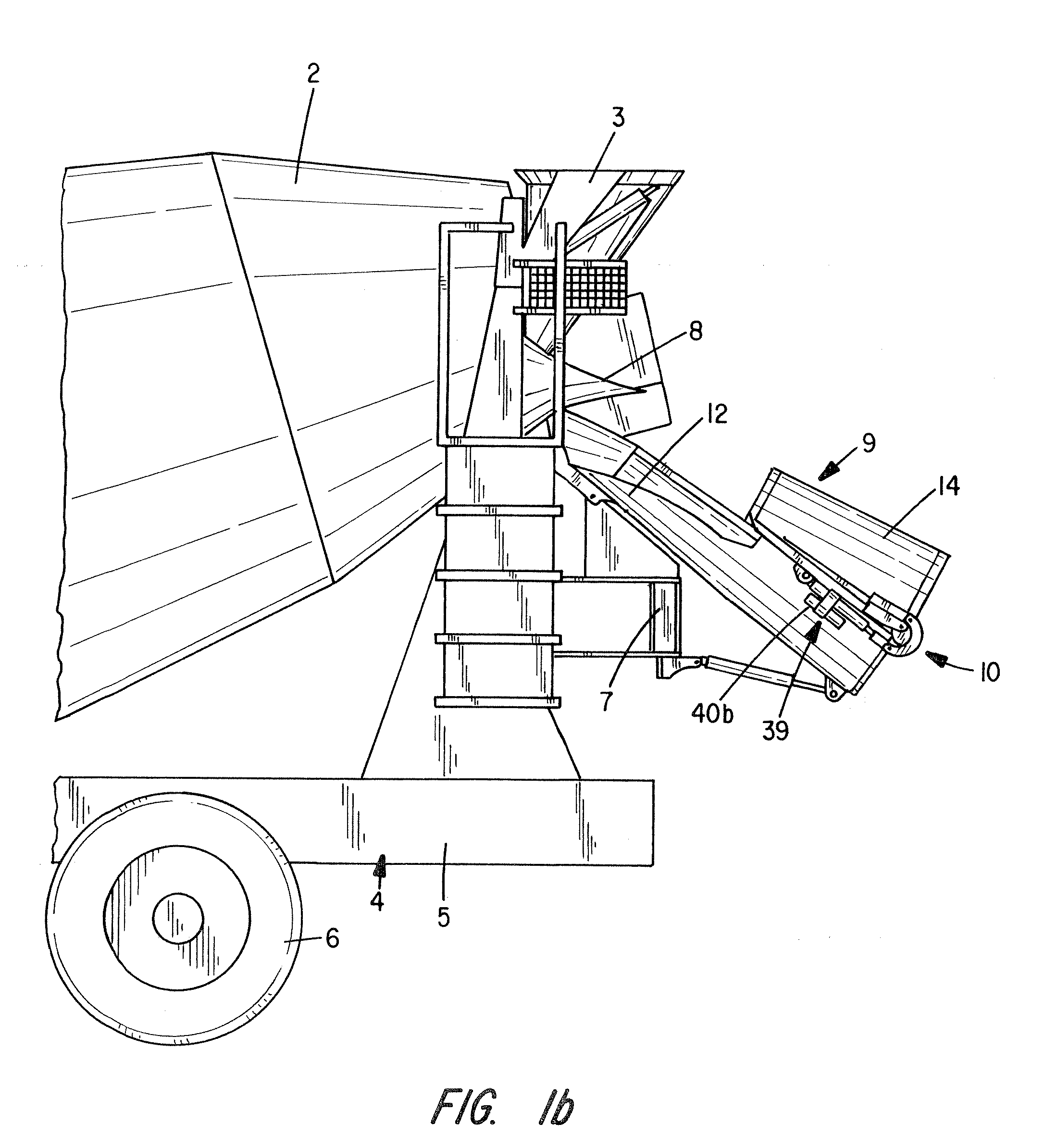
[0022]As illustrated in FIGS. 1a and 1b, the embodiments of the current invention movably attach to a conventional transit concrete mixing truck which possesses a mi...


PUM

PropertyMeasurementUnit
forceaaaaaaaaaa
torsional forcesaaaaaaaaaa
forcesaaaaaaaaaa

Abstract

The hinge assembly of the present invention is a novel configuration that utilizes multiple arcuate shaped clevis elements. The configuration produces a compact, stable, and efficient means for transmitting an actuation force to retract or deploy one or more sections of a folding chute assembly utilized on transit concrete mixing vehicles.

Description

CROSS-REFERENCED TO RELATED APPLICATIONS[0001]Not applicableSTATEMENT REGARDING FEDERALLY SPONSORED RESEARCH OR DEVELOPMENT[0002]Not applicableTECHNICAL FIELD[0003]The invention relates generally to transit concrete mixing and delivery vehicles and, more particularly, to a multi-component linkage assembly for a concrete chute attached to a concrete mixer. The invention is particularly suited for manipulating a folding concrete chute from a stored (folded) configuration to a deployed configuration and back again.BACKGROUND OF THE INVENTION[0004]It is common for transportable mixing units, like those employed on concrete trucks, to use a plurality of hinged chute sections, for movement between a retracted transport position and an extended discharge position, and for the transfer and discharge of concrete mix from a transport vehicle. It is well known in the art that a variety of hydraulically, pneumatically, or electrically driven assemblies are available to actuate the chute deploym...

Claims


Application Information

Patent Timeline
Patent Type & Authority Patents(United States)
IPC IPC(8): B65G11/00
CPCB28C5/4251B65G11/186
Inventor SHABER, KEVIN M.LINDBLOM, THOMAS G.
Owner LMI US LLC
Why Eureka
Try Eureka