
Vehicular suspension device

a technology of suspension device and suspension spring, which is applied in the direction of resilient suspension, vehicle spring, vehicle components, etc., can solve the problems of inability to ensure favorable handling stability, inability to adequately perform the action of the stabilizer, and deterioration of the lever ratio, so as to improve the camber change during a reverse-phase stroke, improve the handling stability, and improve the effect of turning performan

Active Publication Date: 2011-11-08
HONDA MOTOR CO LTD
View PDF13 Cites 7 Cited by
  • Summary
  • Abstract
  • Description
  • Claims
  • Application Information

AI Technical Summary

Benefits of technology

The present invention provides a vehicle suspension apparatus that can achieve both high toe rigidity and ideal camber angle change while ensuring favorable handling stability during a turn. This is achieved by connecting the upper arm, damper unit, and stabilizer in a specific order to the knuckle, which allows for the use of the reaction force of the stabilizer as a moment in a camber direction and create interference in the camber direction. This results in improved handling stability and turning performance. The arm configuration also allows for a common multilink suspension design, expanding the degree of freedom in designing the suspension apparatus.

Problems solved by technology

Here, when the ratio between the distance from the knuckle on the lower arm to the input point of the stabilizer and the distance from the input point of the stabilizer to the vehicle body side of the lower arm is designated as a lever ratio, the lever ratio deteriorates with increased distance from the knuckle on the lower arm to the input point of the stabilizer, and sometimes the action of the stabilizer cannot be adequately performed.
Specifically, it is impossible to assure favorable handling stability.

Method used


Image

  • Vehicular suspension device
  • Vehicular suspension device
  • Vehicular suspension device

Examples


Embodiment Construction

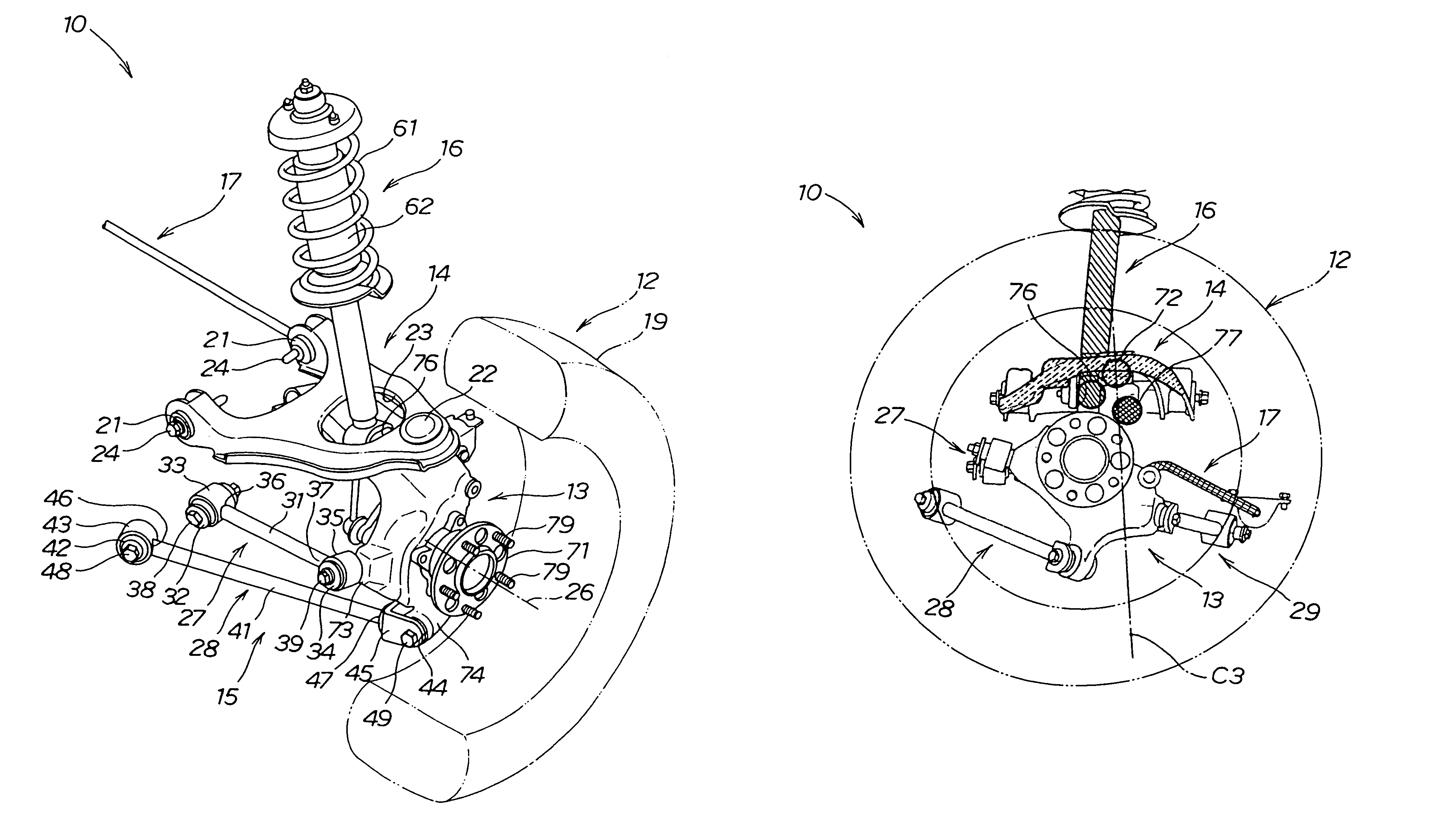
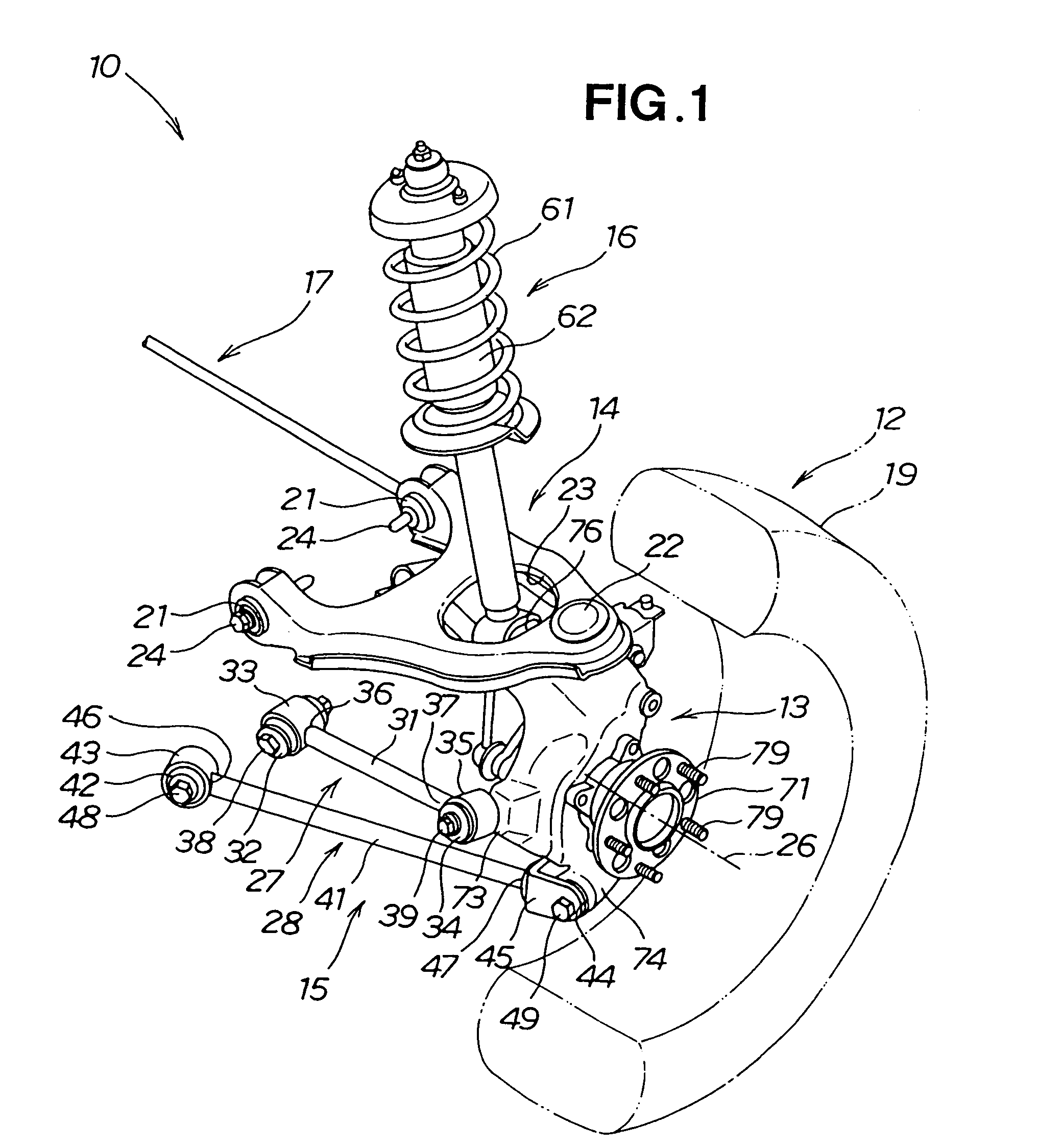
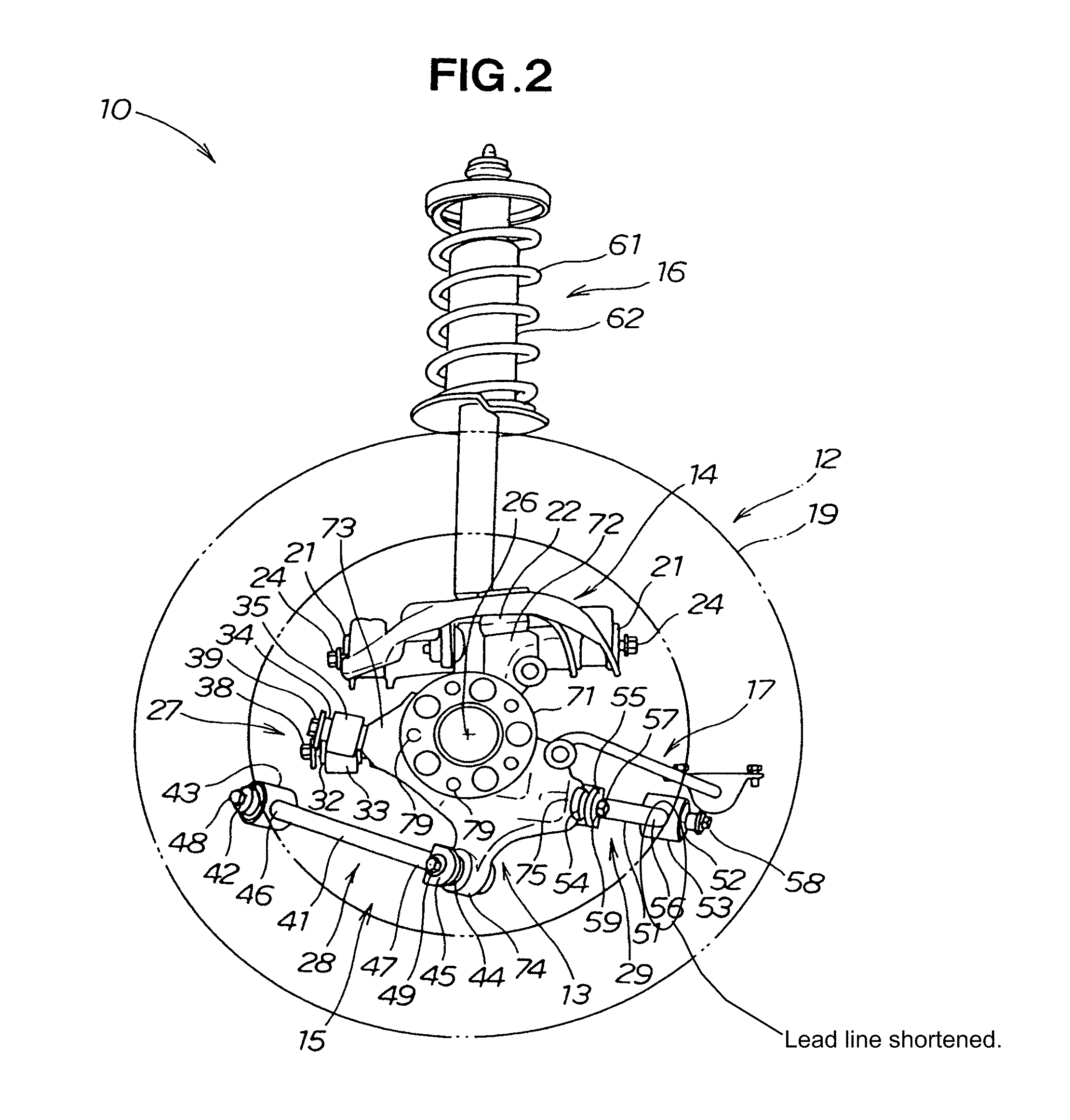
[0029]As shown in FIGS. 1 to 4, the vehicle suspension apparatus 10 is a rear suspension for a right rear wheel (vehicle wheel) 12. The apparatus has a knuckle 13 to which the wheel 12 is attached in a freely rotating manner, an upper arm 14 extending from the inner side of the vehicle body outward widthwise relative to the vehicle body and supporting the upper portion of the knuckle 13, a lower arm 15 extending from the inner side of the vehicle body outward widthwise relative to the vehicle body and supporting the lower portion of the knuckle 13, a damper unit (shock absorber) 16 extending between the vehicle body and the upper portion of the knuckle 13 and softening shocks input from the wheel 12, and a stabilizer 17 extending between the vehicle body and the upper portion of the knuckle 13 and stabilizing the vehicle body. As shown in FIG. 4, the stabilizer 17 is operatively connected to the knuckle 13 via a substantially vertically oriented linking member 18 extending therebetw...


PUM


Abstract

A suspension apparatus is disclosed for which vehicle handling stability can be obtained. An upper arm (14), a damper unit (16), and a stabilizer (17) are connected in this order to a knuckle (13) from outside of the vehicle body in a width direction of the vehicle body. The reaction force of the stabilizer is used as a moment in the camber direction, and causes interference in the camber direction. As a result, a camber change during a reverse phase stroke is increased over a camber change during a same-phase stroke, and turning performance of the vehicle is improved.

Description

TECHNICAL FIELD[0001]The present invention relates to a vehicle suspension apparatus for allowing a wheel to move up and down in a stroke to soften an input from a road surface and keep the vehicle stable.BACKGROUND ART[0002]Double-wishbone and multilink suspension apparatuses are known as vehicle suspension apparatuses.[0003]These types of suspension apparatuses have been widely adopted with design modifications to the suspension according to different applications.[0004]Known as these vehicle suspension apparatuses are those in which a knuckle is supported with a damper unit, those in which input from a stabilizer is introduced into a lower arm, and those in which input from a stabilizer is introduced into an upper arm (for example, Japanese Patent Application Laid-Open Publication Nos. 2006-143013, 2000-153705 and 2006-182174).[0005]FIG. 8 hereof shows the suspension apparatus disclosed in Japanese Patent Application Laid-Open Publication No. 2006-143013.[0006]In a suspension app...

Claims


Application Information

Patent Timeline
Patent Type & Authority Patents(United States)
IPC IPC(8): B60G3/18
CPCB60G3/20B60G3/265B60G2200/18B60G2204/148B60G2202/31B60G2204/1224B60G2200/46
Inventor HIRAI, HIDEKI
Owner HONDA MOTOR CO LTD
Learn More