Method for manufacturing light reflecting metal wall

a technology of metal wall and light reflection, which is applied in the direction of optical articles, electroluminescent light sources, other domestic articles, etc., can solve the problems of end product problems, damage to the light reflection metal wall b>704/b>, and difficulty in forming the required shape of the opening portion of the light reflection surfa

Active Publication Date: 2011-11-08
SHARP KK +1
View PDF9 Cites 2 Cited by
  • Summary
  • Abstract
  • Description
  • Claims
  • Application Information

AI Technical Summary

Benefits of technology

[0031]Therefore, the wet etching is carried out with respect to the surface of the metal plate while the rim of the opening portion of the cavity structure is protected with the first mask. Thus, (i) it is possible to stably keep the shape and strength of the manufactured metal plate while the thickness between the outer circumferential wall and the light reflecting wall on the cavity structure side is kept to a thickness of not less than a predetermined one and (ii) it is possible to secure the bottom width of the bottom part in the cavity structure of the metal plate while the opening width of the opening portion is suppressed.
[0033]And, with this etching method, the light reflecting wall is arranged such that the opening portion is made smaller than the center part, thereby preventing a material (such as a resin material), which fills the cavity structure of the metal plate from coming off.

Problems solved by technology

Therefore, when the light reflecting metal wall 704 has a thin thickness B, there is a possibility that the light reflecting metal wall 704 is damaged during the cutting.
Further, in cases where the light-emitting element is the one obtained by being individually cut, when the light reflecting metal wall 704 has a thin thickness t, this also causes some problem in view of an end product.
It is difficult to form a required shape of the opening portion of the light reflecting surface, because metal is a material which is etched isotropically.
This causes the area of the LED chip mounting not to be secured sufficiently.
This arises a problem that a shape of the light reflecting metal wall 704 can not be kept due to lack of strength.

Method used


Image

  • Method for manufacturing light reflecting metal wall
  • Method for manufacturing light reflecting metal wall
  • Method for manufacturing light reflecting metal wall

Examples


Embodiment Construction

[0058]One embodiment of the present invention is described below referring to drawings.

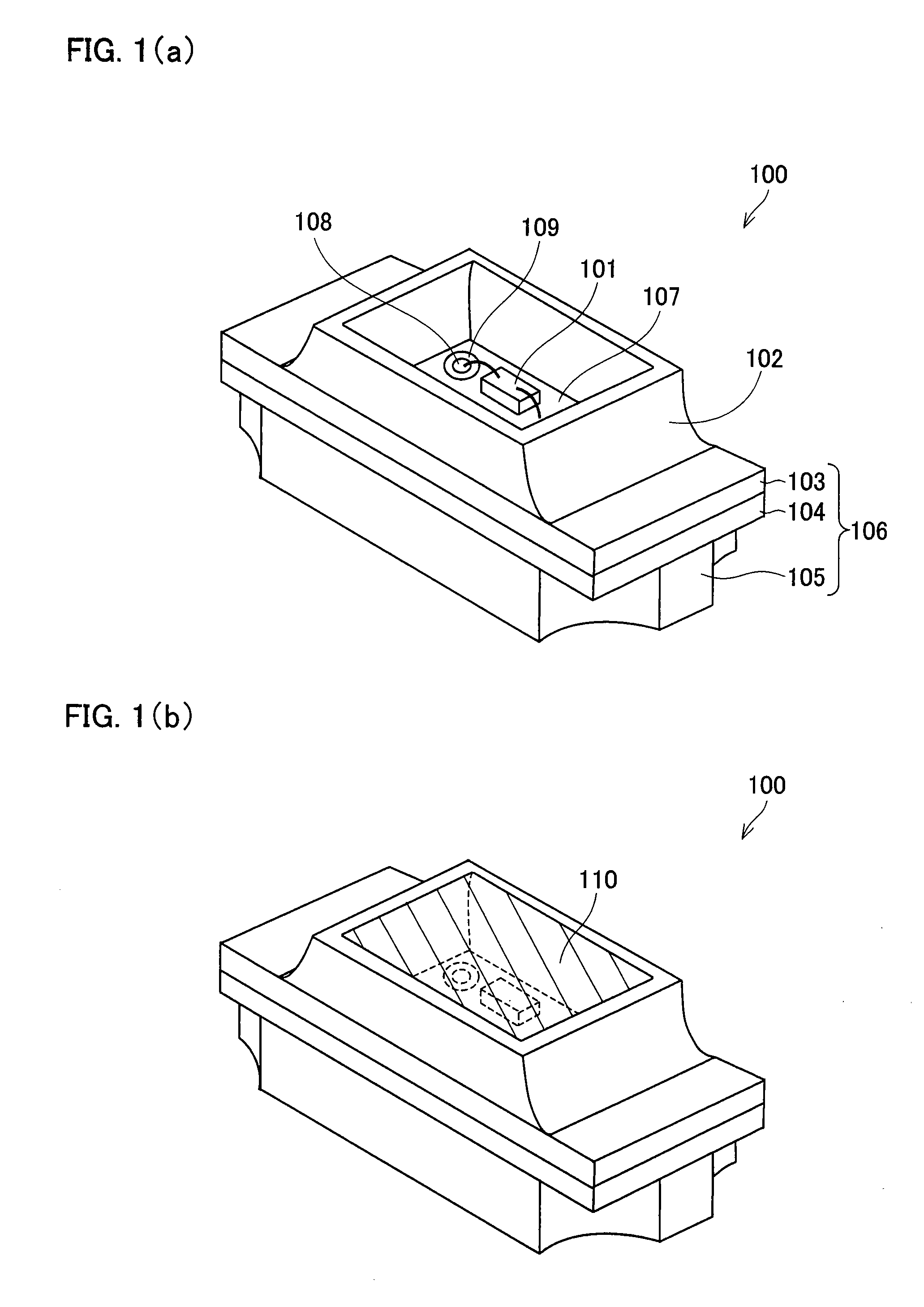
[0059]FIG. 1(a) illustrates an example of an arrangement of a light-emitting element 100 in which no translucent sealing body 110 has been provided yet, and FIG. 1(b) is a perspective view illustrating an example of an arrangement of the light-emitting element 100 in which a translucent sealing body 110 has been already provided.

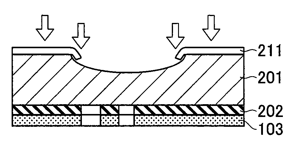
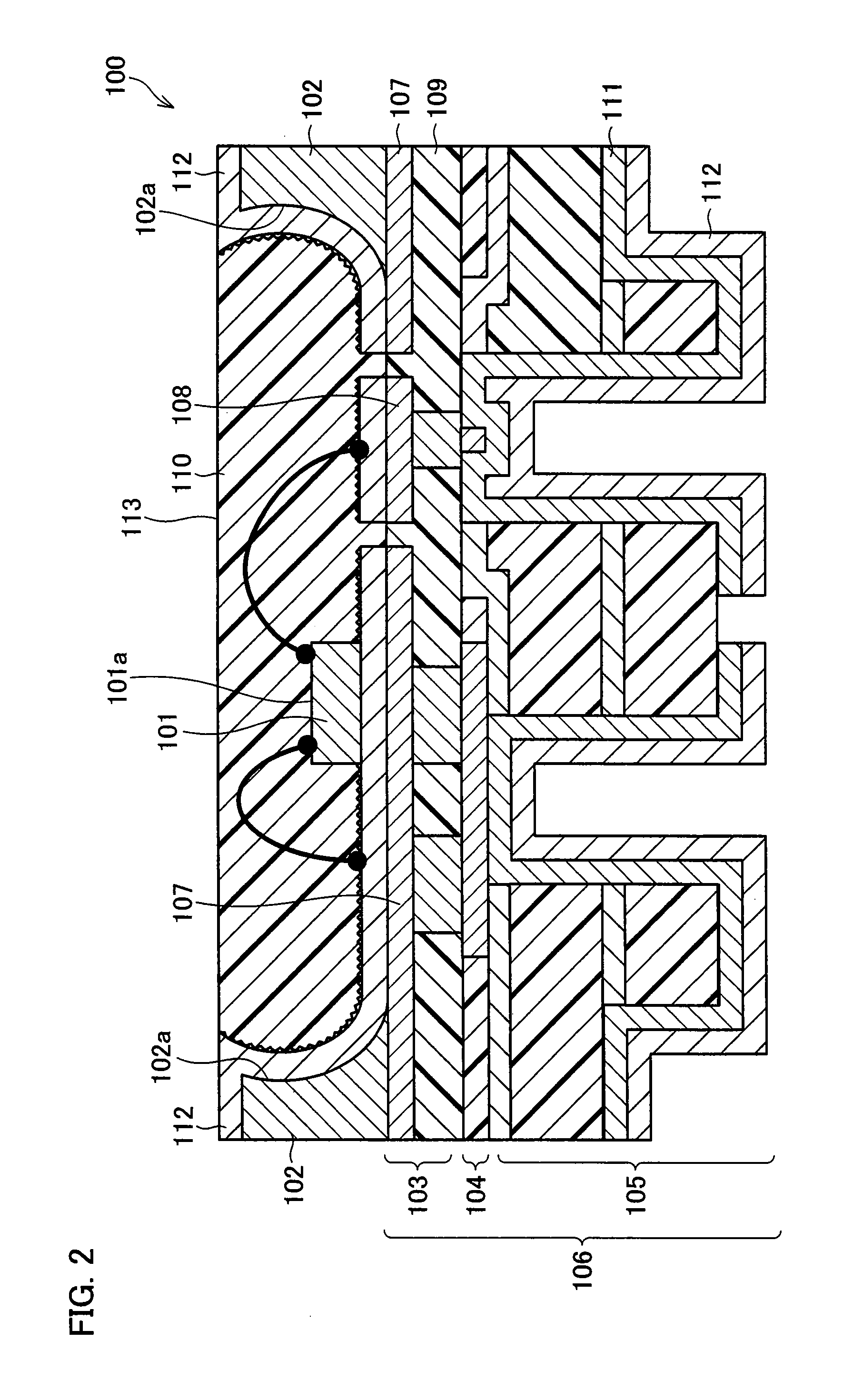
[0060]FIG. 2 is a side cross-section view illustrating an arrangement of the light-emitting element 100 in detail.

[0061]The light-emitting element 100 in accordance with the present embodiment is arranged such that its light outgoing surface is provided so as to face a side surface of a liquid crystal panel which is provided to a display screen of a mobile phone or the like. In short, the light-emitting element 100 is used as a backlight for irradiating the liquid crystal panel from the side of the liquid crystal panel.

[0062]As illustrated in FIGS. 1(a) and 1(b), the light...


PUM

PropertyMeasurementUnit
thicknessaaaaaaaaaa
heightaaaaaaaaaa
heightaaaaaaaaaa

Abstract

A method for manufacturing a light reflecting metal wall including a step (a) forming a cavity structure on a metal plate on which back surface a substrate is laminated, the cavity structure including on its side wall a light reflecting wall, the step (a) including the steps of (b) forming a first mask on a surface of the metal plate, the first mask having a mask opening portion corresponding to an opening portion of the cavity structure, and (c) forming the light reflecting wall on a side wall of the metal plate by carrying out wet etching with respect to the metal plate with the first mask, in the step (c), in the middle of the wet etching, the first mask being bent by press working along the light reflecting wall formed by the wet etching. As a result, the light reflecting metal wall is stably formed by securing both (i) an area of an LED chip mounting surface and (ii) a thickness of the light reflecting metal wall even if a packaged light-emitting element has a narrow lateral width of its short side.

Description

[0001]This Nonprovisional application claims priority under U.S.C. §119(a) on Patent Application No. 132188 / 2007 filed in Japan on May 17, 2007, the entire contents of which are hereby incorporated by reference.FIELD OF THE INVENTION[0002]The present invention relates to a method for manufacturing a light reflecting metal wall of a light-emitting element which is suitable for irradiating a thin display body, such as a liquid crystal panel, from a side of the display body.BACKGROUND OF THE INVENTION[0003]Conventionally, a light-emitting element such as a Light Emitting Diode (hereinafter, referred to as LED) is used as a light source of a backlight for irradiating a display panel, such as a liquid crystal display panel, from a side of the display panel. Light-emitting elements adopting various arrangements have been proposed so that light emitted from the LED is efficiently taken out from the light-emitting elements.[0004]For example, FIGS. 10(a) and 10(b) illustrates a light-emittin...

Claims


Application Information

Patent Timeline
Patent Type & Authority Patents(United States)
IPC IPC(8): C25F5/00H01L33/60
CPCH01L33/60H01L24/85Y10T29/49167H01L2224/48091H01L2224/48235H01L2224/48464H01L2924/01013H01L2924/01029H01L2924/01078H01L2924/01079H01L2924/15153H01L33/486H01L2224/85H01L2924/00014H01L2924/12041H01L24/48H01L2924/00H01L2224/45015H01L2924/207H01L2224/45099
Inventor TAKEMOTO, MASASHITAKAHASHI, SYUJIWAKAMATSU, TOMIOOGAWA, YOSHITERU
Owner SHARP KK
Why Eureka
Try Eureka