Tensioning of the top roll of a crop conditioner

a crop conditioner and top roll technology, applied in the field of crop conditioner top roll tensioning, can solve the problems of crop stem wax cracking, achieve the effects of reducing the amount of sand on the crop stem, and improving the quality of crop conditioner

Active Publication Date: 2011-11-15
MACDON INDS
View PDF26 Cites 32 Cited by
  • Summary
  • Abstract
  • Description
  • Claims
  • Application Information

AI Technical Summary

Benefits of technology

[0035]Thus, as described in more detail hereinafter, the roller tension spring is mounted in a generally vertical configuration. The spring pulls on the bell crank which applies a downward force on the top conditioner roll arm via the tension link. The plane of action of the tension mechanism is generally perpendicular to the plane of action of the roll mounting mechanism. The tension adjustment of the downward pressure on the top conditioner roll can be adjusted easily from the top of the header, close to the location of the roll gap adjustment.
[0036]The bell crank system allows for better control of down force applied to the top conditioner roll arm through opening range.
[0037]The arrangement which causes the tension mechanism to operate perpendicular to the roll support mechanism allows for more optimal spatial design and an easier adjustment of roll down force.

Problems solved by technology

The intermeshing of the flutes causes the crop material to be bent as it passes between the rollers causing a cracking of the waxy surface of the crop stem.

Method used


Image

  • Tensioning of the top roll of a crop conditioner
  • Tensioning of the top roll of a crop conditioner
  • Tensioning of the top roll of a crop conditioner

Examples


Embodiment Construction

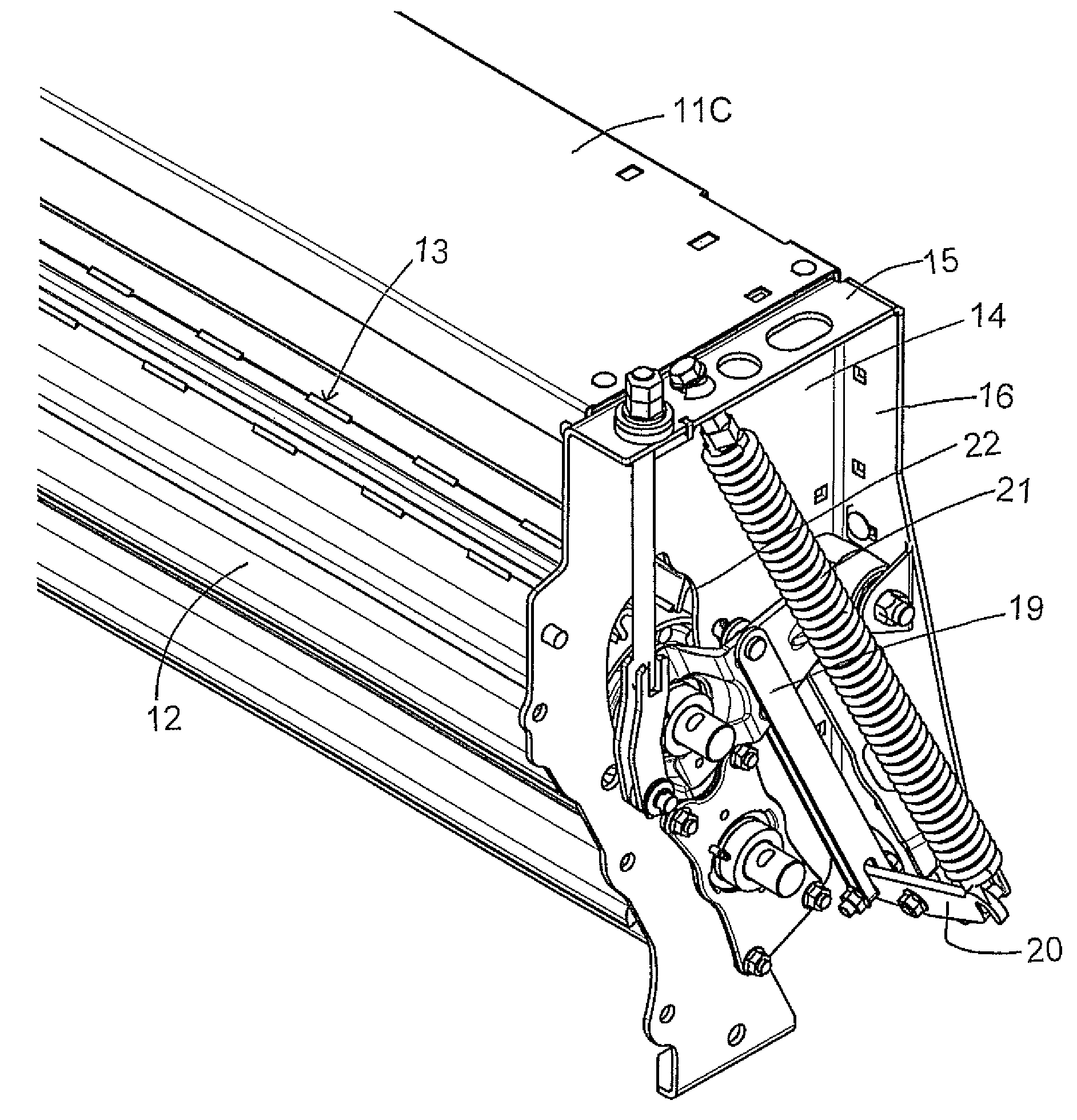
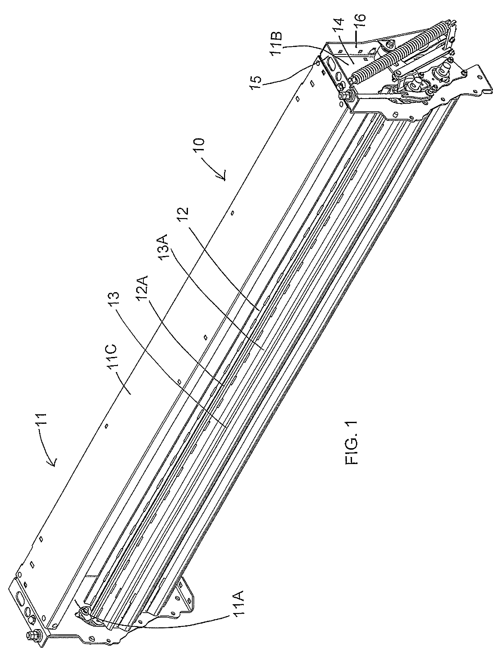
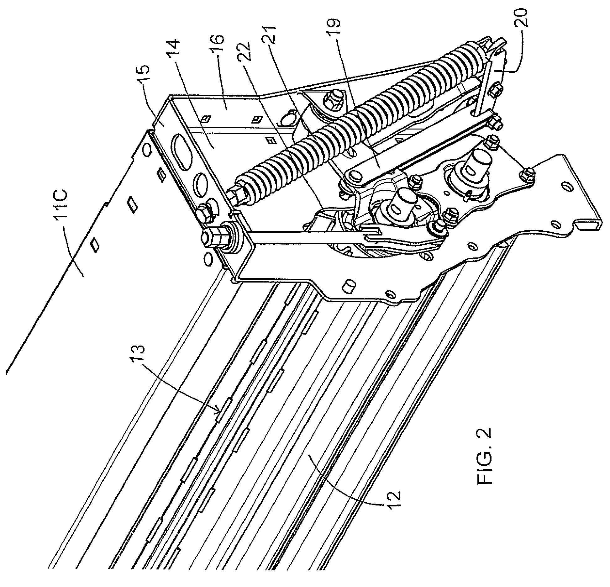
[0049]A conditioner 10 for conditioning cut crop material from a harvester is shown in the figures and is arranged to be mounted behind the cutter bar of a harvesting machine with a discharge opening of the machine.

[0050]Examples of machines of this type are disclosed in the following documents of the present Assignees.

[0051]U.S. Pat. No. 7,340,876 issued Mar. 11, 2008 which corresponds to US Published Application 2008 / 0066440 filed Sep. 15, 2006 and published Mar. 23, 2008 and to Canadian application 2,559,353 discloses an arrangement which provides impellers of an hour glass shape arranged at the outer cutter disks. The disclosure of this document is incorporated herein by reference.

[0052]U.S. Pat. No. 7,454,888 issued Nov. 25, 2008 which corresponds to US Published Application 2008 / 0066441 filed Sep. 15, 2006 and published Mar. 23, 2008 and to Canadian application 2,559,217 discloses an arrangement which provides a transfer roller between the cutter disks and the conditioning rol...


PUM


Abstract

A crop conditioner includes a frame mounting a bottom fixed roller and a top liftable roller. The top roller is liftable at each end on a pivot member tensioned by a tension link, a tension spring and a bell crank connected between the tension link and the spring. The bell crank is mounted on the conditioner frame for pivotal movement about a pivot axis which lies transversely to a line parallel to the pivot axis of the second roller so that the bell crank extends from the tension link to the tension spring in a direction outwardly of the radial plane of the roller pivot axis. The spring extends upwardly and forwardly from the bell crank pivot at a rear flange of the frame to an adjustment screw of the spring at a top flange of the frame immediately adjacent an adjustment of a bottom stop of the top roller.

Description

[0001]This invention relates to a crop conditioner including two generally parallel rolls forming a nip through which the crop passes with one of the rollers being movable to increase the width of the nip, and particularly to a tensioning arrangement for applying tension to the movable roller.BACKGROUND OF THE INVENTION[0002]Hay conditioners generally include a pair of rollers mounted in co-extensive parallel relationship for rotation about respective axes with the crop arranged to pass between the rollers in a conditioning action.[0003]Each of the rollers generally carries a plurality of longitudinally extending angularly spaced flutes which project outwardly from the surface of the roller. The rollers are spaced by a set distance at the nip such that the flutes intermesh generally without contact between the rollers. The intermeshing of the flutes causes the crop material to be bent as it passes between the rollers causing a cracking of the waxy surface of the crop stem.[0004]It i...

Claims


Application Information

Patent Timeline
Patent Type & Authority Patents(United States)
IPC IPC(8): A01D61/00
CPCA01D82/00
Inventor BARNETT, NEIL GORDON
Owner MACDON INDS
Why Eureka
Try Eureka