Method of radially expanding a tubular element in a wellbore provided with a control line

a control line and tubular element technology, applied in the direction of borehole/well accessories, sewer pipelines, mechanical devices, etc., can solve the problems of high friction force that needs to be overcome, and the expander becomes stuck in the tubular element, so as to increase the collapse resistance of the expanded tubular section

Active Publication Date: 2011-11-15
SHELL OIL CO
View PDF15 Cites 13 Cited by
  • Summary
  • Abstract
  • Description
  • Claims
  • Application Information

AI Technical Summary

Benefits of technology

[0011](b) increasing the length of the expanded tubular section by inducing the bending zone to move in axial direction relative to the remaining tubular section, wherein said wall includes a material that is plastically deformed in the bending zone during the bending process so that the expanded tubular section retains an expanded shape as a result of said plastic deformation; and
[0013]Thus, in effect the tubular element is everted, i.e. turned inside out during the bending process. The bending zone defines the location where the bending process takes place. By inducing the bending zone to move in axial direction along the tubular element it is achieved that the tubular element is progressively expanded without the need for an expander that has to be pushed, pulled or pumped through the tubular element. Furthermore the expanded tubular section retains its shape due to plastic deformation of the wall, that is, permanent deformation of the wall. It is thereby achieved that no external force or pressure needs to be exerted to the expanded tubular section to maintain its expanded shape. If, for example, the expanded tubular section has been expanded against the wellbore wall as a result of the bending process, no external radial force or pressure needs to be exerted to the expanded tubular section to keep it against the wellbore wall.
[0022]If the bending zone is located at a lower end of the tubular element, whereby the remaining tubular section is axially shortened at a lower end thereof due to said movement of the bending zone, it is preferred that the remaining tubular section is axially extended at an upper end thereof in correspondence with said axial shortening at the lower end thereof. The remaining tubular section gradually shortens at its lower end due to continued reverse bending of the wall. Therefore, by extending the remaining tubular section at its upper end to compensate for shortening at the lower end, the eversion process can be continued until a desired length of the expanded tubular section is reached. The remaining tubular section can be extended at its upper end, for example, by connecting one or more tubular portions at the upper end such as by welding. Alternatively, the remaining tubular section can be formed as a coiled tubing that is unreeled from a reel and gradually inserted into the wellbore. Thus, in effect the coiled tubing is extended at its upper end by unreeling from the reel.
[0023]As a result of forming the expanded tubular section around the remaining tubular section, an annular space is formed between the unexpanded and expanded tubular sections. To increase the collapse resistance of the expanded tubular section, a pressurized fluid can be inserted into the annular space. The fluid pressure can be due to the weight of the fluid column in the annular space, and / or from an external pressure applied to the fluid column.

Problems solved by technology

Such method can lead to high friction forces that need to be overcome, between the expander and the inner surface of the tubular element.
Also, there is a risk that the expander becomes stuck in the tubular element.

Method used


Image

  • Method of radially expanding a tubular element in a wellbore provided with a control line
  • Method of radially expanding a tubular element in a wellbore provided with a control line
  • Method of radially expanding a tubular element in a wellbore provided with a control line

Examples


Embodiment Construction

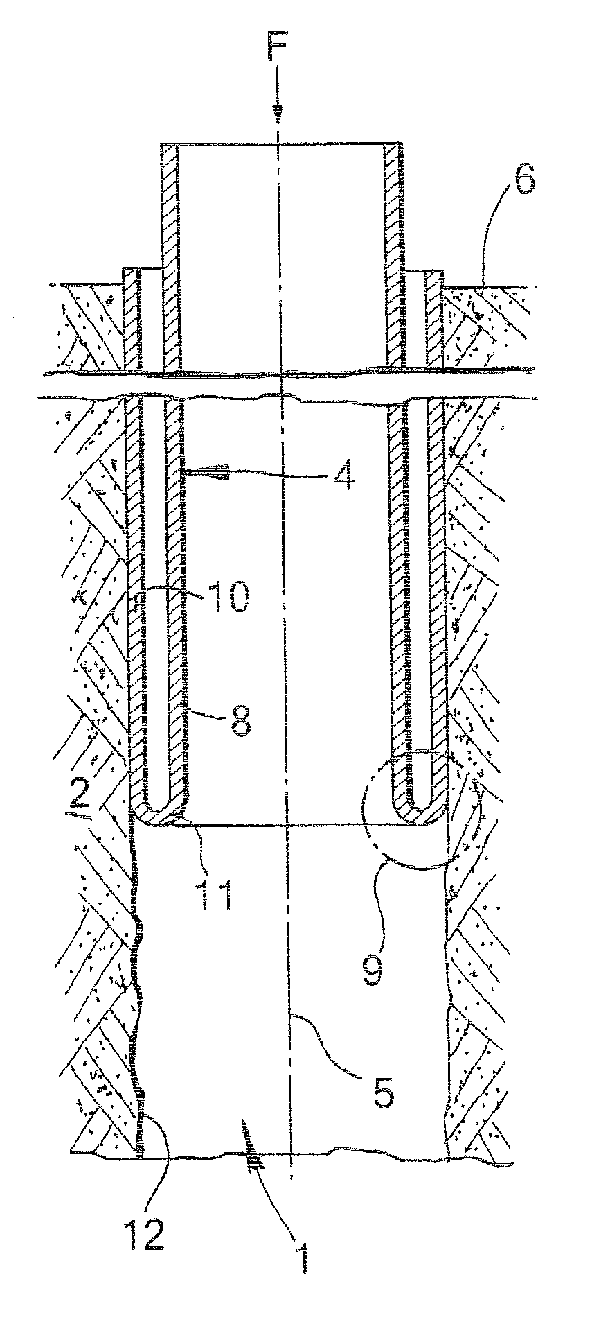
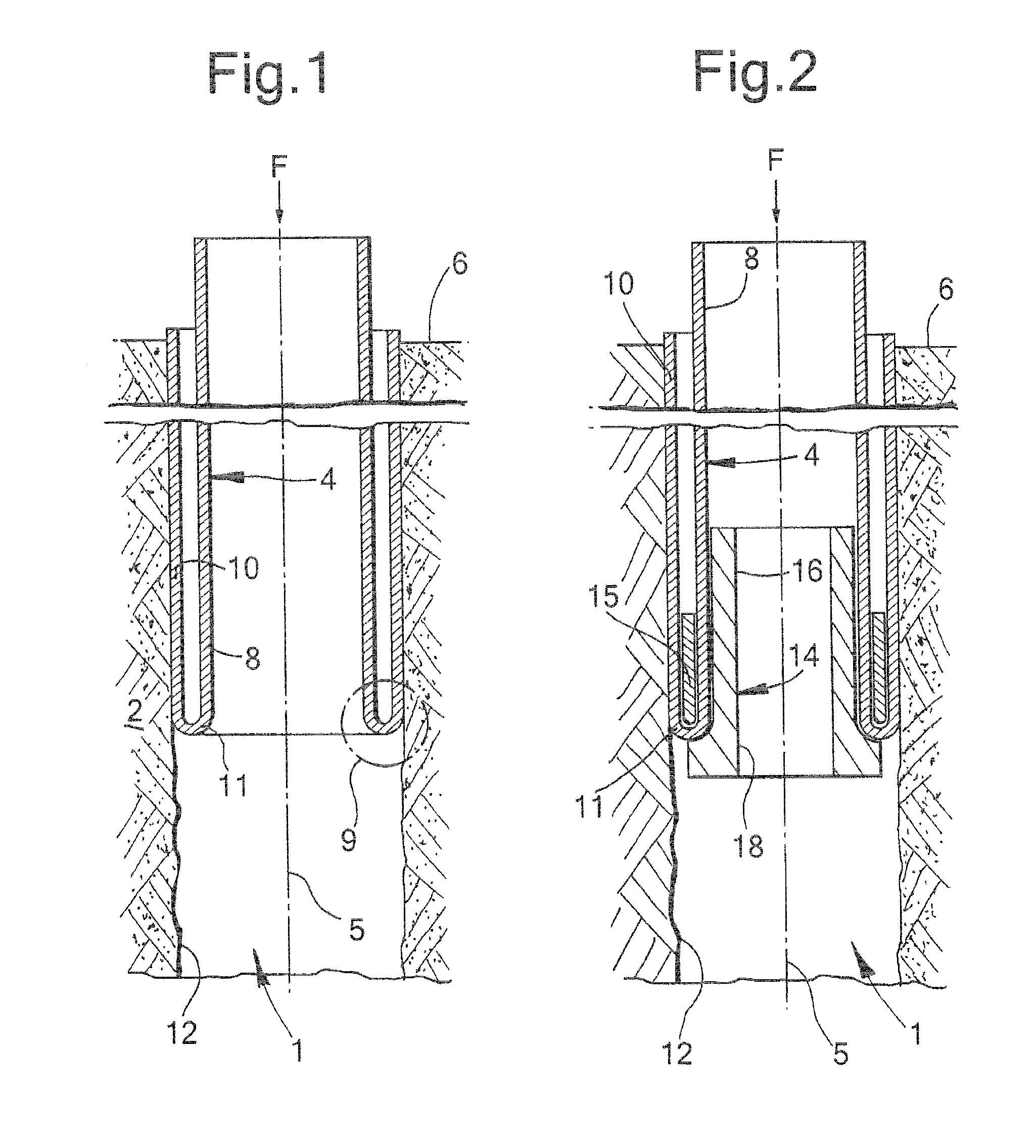
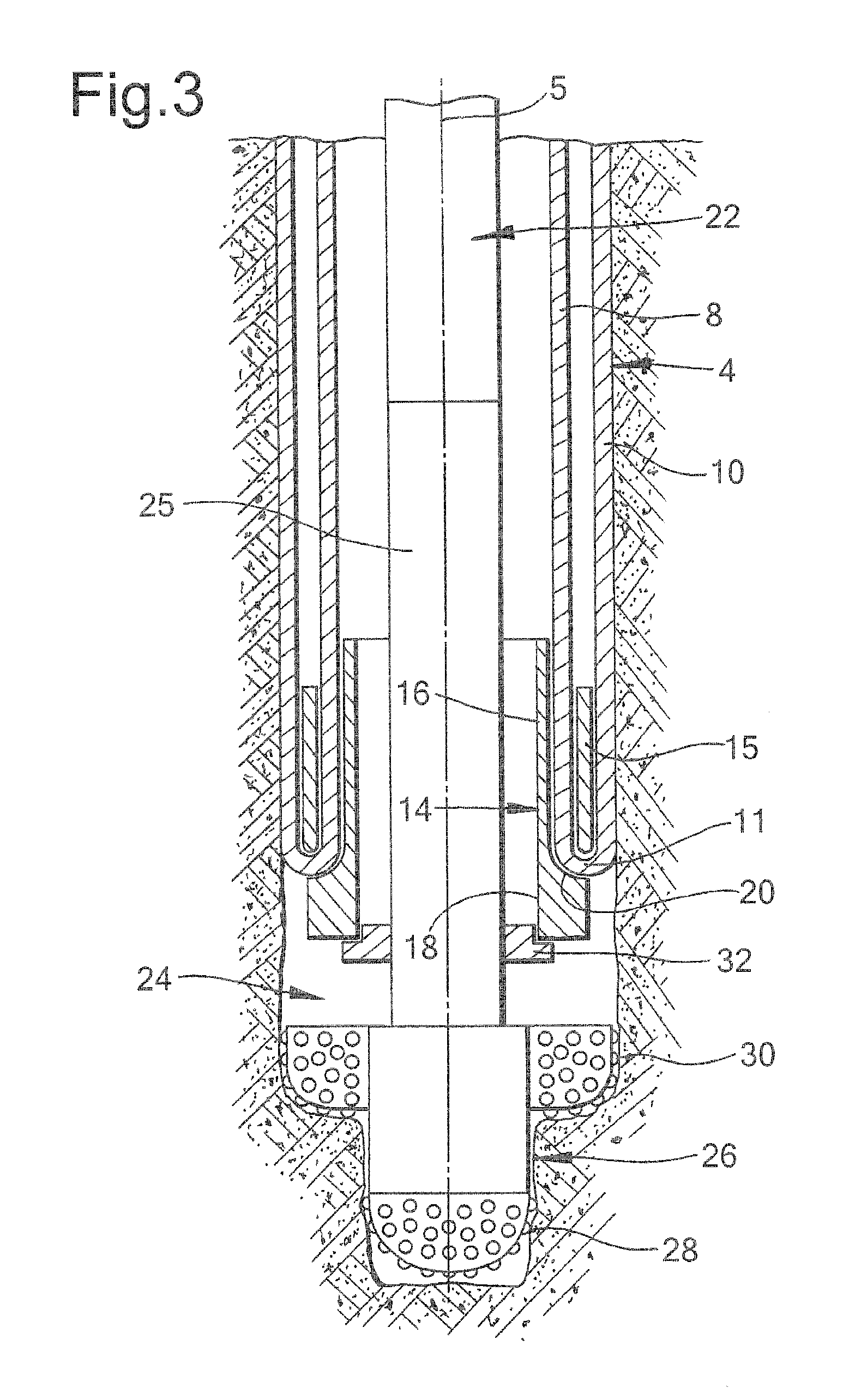
[0039]Referring to FIG. 1 there is shown a system comprising a wellbore 1 formed into an earth formation 2, and a radially expandable tubular element in the form of an expandable steel liner 4 extending from surface 6 downwardly into the wellbore 1, the liner having a central longitudinal axis 5. The liner 4 has a radially expanded tubular section 10 and a remaining tubular section in the form of unexpanded section 8 extending within the expanded section 10. The wall of the unexpanded section 8 bends, at its lower end, radially outward and in axially reverse (i.e. upward) direction so as to form a U-shaped lower section 11 interconnecting the unexpanded section 8 and the expanded section 10. The U-shaped lower section 11 defines a bending zone 9 of the tubular element 4. The expanded liner section 10 is axially fixed to the wellbore wall 12 by virtue of frictional forces between the expanded section 10 and the wellbore wall 12 due to compression of the expanded section 10 against th...


PUM


Abstract

A method for radially expanding a tubular element in a wellbore and providing a control line that extends along the tubular element comprises (a) inducing the wall of the tubular element to bend radially outward and in axially reverse direction so as to form an expanded tubular section extending around a remaining tubular section of the tubular element, wherein said bending occurs in a bending zone of the tubular element, (b) increasing the length of the expanded tubular section by inducing the bending zone to move in axial direction relative to the remaining tubular section, wherein said wall includes a material that is plastically deformed in the bending zone during the bending process so that the expanded tubular section retains an expanded shape as a result of said plastic deformation, and (c) extending the control line along the tubular element.

Description

RELATED CASES[0001]The present application is a continuation of and claims priority to PCT Application EP2008 / 064163, filed 21 Oct. 2008, which in turn claims priority from European Application EP07119090.4, filed 23 Oct. 2007.FIELD OF THE INVENTION[0002]The present invention relates to a method of radially expanding a tubular element in a wellbore, in which a control line extends along the tubular element.BACKGROUND OF THE INVENTION[0003]In the industry of oil and gas production from a wellbore it has become practice to radially expand a tubular element in the wellbore. Generally a wellbore is provided with one or more casings or liners to provide stability to the wellbore wall, and / or to provide zonal isolation between different layers of the earth formation. The terms “casing” and “liner” refer to tubular elements for supporting and stabilising the wellbore wall, whereby it is generally understood that a casing extends from surface into the wellbore and that a liner extends from ...

Claims


Application Information

Patent Timeline
Patent Type & Authority Patents(United States)
IPC IPC(8): E21B19/00
CPCE21B7/20E21B17/1035E21B43/103F16L55/1651
Inventor KRIESELS, PETRUS CORNELISVAN NIEUWKOOP, PIETER
Owner SHELL OIL CO
Why Eureka
Try Eureka