Squeeze foamer

a foamer and squeeze technology, applied in the field of squeeze foamers, can solve the problems of unsatisfactory foam quality, unoptimum air and liquid quality, and complex known dispensing devices

Active Publication Date: 2011-11-15
REXAM AIRSPRAY
View PDF9 Cites 11 Cited by
  • Summary
  • Abstract
  • Description
  • Claims
  • Application Information

AI Technical Summary

Benefits of technology

[0014]In one embodiment, the housing is substantially circular-symmetrical about a center axis and / or the liquid to be dispensed, during dispensing, moves in a direction relative to the longitudinal direction of the housing. In such an embodiment, the liquid does not have to follow complicated flow paths in which the main direction of the liquid is reversed two times or more. This also allows a relatively simple construction of the dispensing device.
[0016]By arranging a constriction in the dispensing passage it is possible to accelerate in the dispensing passage the foam flow or liquid-air mixture flow. As a result, the mixing and thus the foam-forming is improved. Preferably, the constriction is arranged upstream with respect to a porous element or sieve element arranged in the dispensing passage, so that after the acceleration, the foam or the liquid-air mixture, is put through the porous element or sieve element to improve the forming of the foam. It has been found that the provision of a constriction results in a considerable improvement of the quality of the foam. The cross section surface area of the constriction is preferably less than 75% of the cross section surface area of the dispensing passage, more preferably less than 50%.
[0017]According to a third aspect, the invention provides a dispensing device for dispensing a foam, which is characterized by the fact that the valve body comprises a through-opening which forms part of the dispensing passage. By allowing the liquid to flow through the through-opening in the valve body, it is not necessary to turn the liquid passage and the air passage around twice in order to achieve communication with the dispensing passage. This results in a relatively simple construction of the dispensing device.

Problems solved by technology

A drawback of the known dispensing device is the fact that the mixture of air and liquid is not optimum, as a result of which the quality of the foam is not satisfactory.
In addition, the structure of the known dispensing device is complex and comprises many components, which makes production complicated.
In addition, the air passage and the liquid passage are bendy, as a result of which the speed of the liquid and air stream decreases, which consequently also leads to a reduction in the quality of the foam.

Method used


Image

  • Squeeze foamer
  • Squeeze foamer
  • Squeeze foamer

Examples


first embodiment

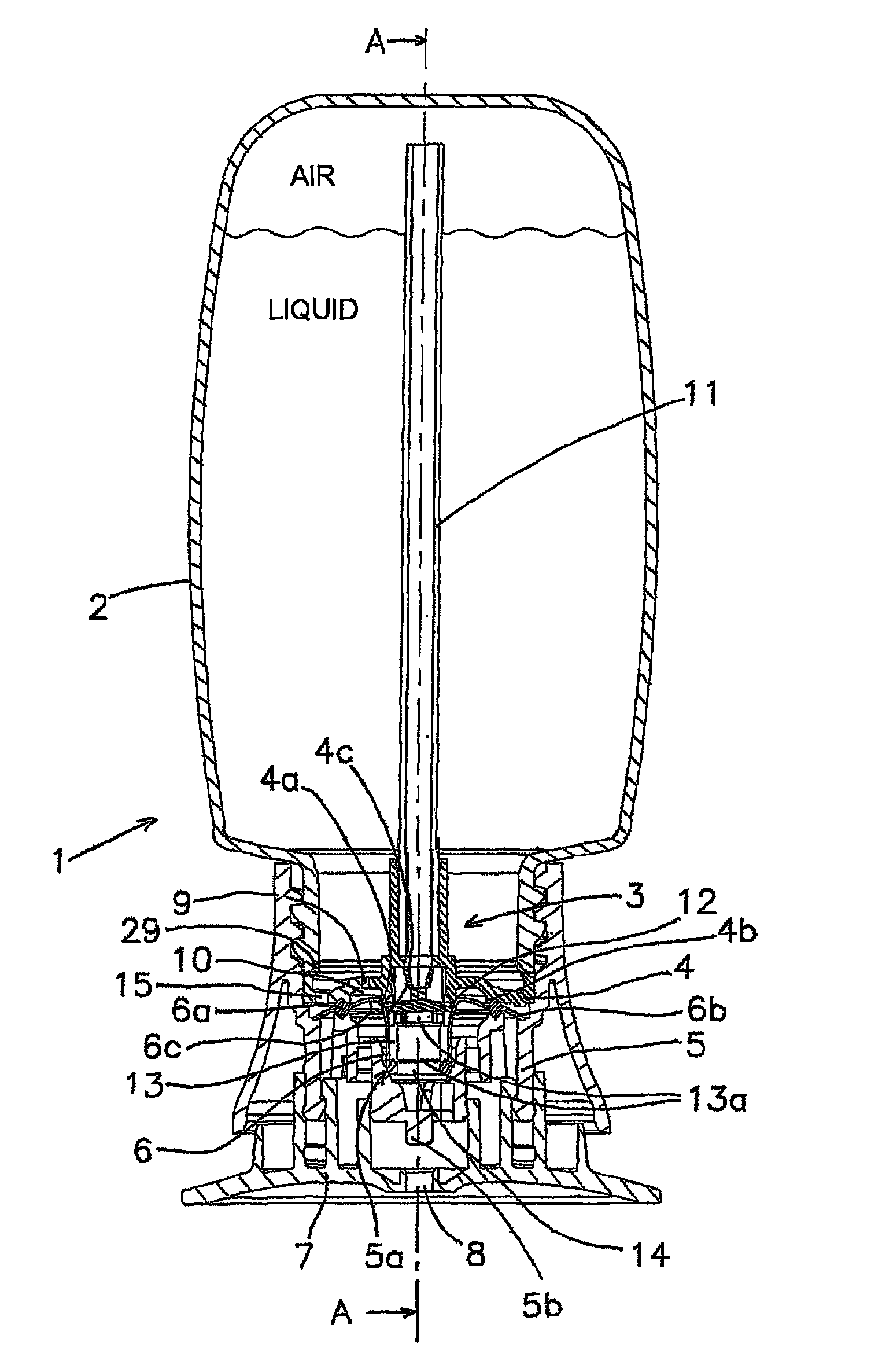
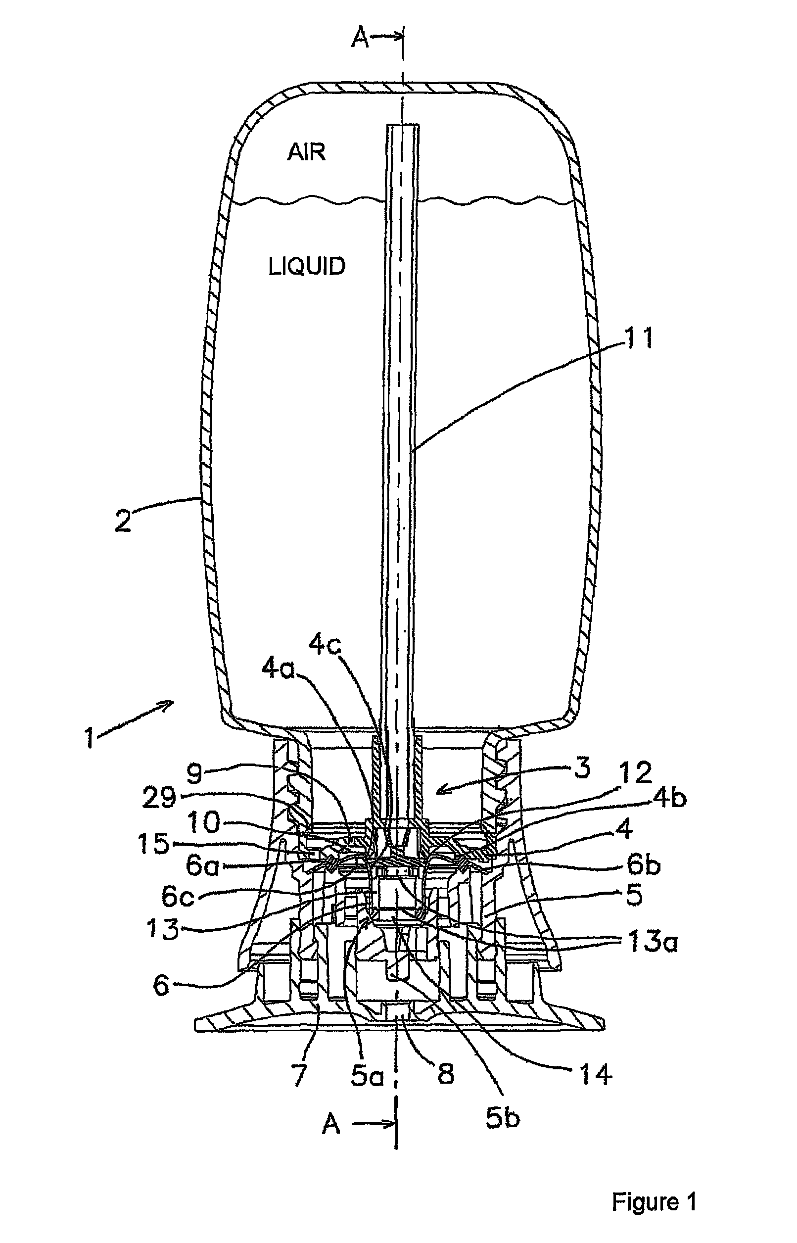
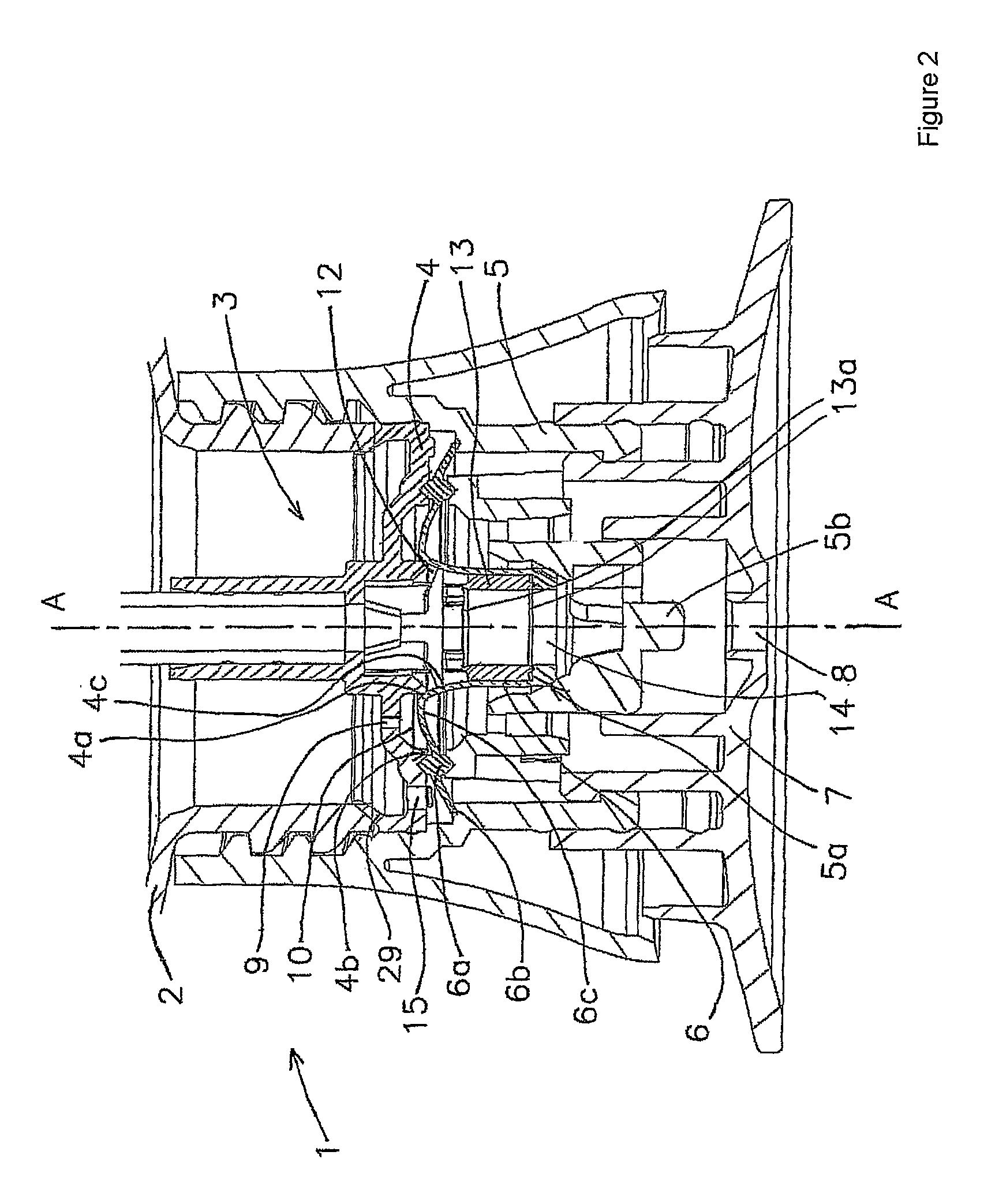
[0027]FIGS. 1 and 2 show a dispensing device according to the invention. The dispensing device is denoted overall by reference numeral 1. The dispensing device 1 is of the squeeze foamer type. Such a squeeze foamer generally dispenses a foam through a dispensing opening as a result of a container being squeezed. After it has been squeezed, the container will return to the original state, either by the elasticity of the container itself or by restoring means which are provided in order to return the container to its original state.

[0028]The foam which can be formed using the dispensing device 1 may be suitable for various different uses, such as, for example, as soap, shampoo, shaving foam, washing-up liquid, sun-tan lotion, after-sun lotion, washing liquid, skincare products and the like.

[0029]The dispensing device is shown in the rest position, that is to say that the container is not being squeezed. Such a squeeze foamer can be operated by hand. However, it is also possible to pus...

second embodiment

[0049]FIG. 3 (i.e. FIGS. 3a and 3b) shows a squeeze foamer according to the invention. This squeeze foamer is generally constructed in accordance with the embodiment shown in FIGS. 1 and 2. Therefore, identical reference numerals have been used to denote substantially identical components of this squeeze foamer. Furthermore, the above-described operation of the squeeze foamer according to FIGS. 1 and 2 generally also applies to the embodiment from FIG. 3.

[0050]The most important difference between the squeeze foamer from FIGS. 1 and 2 and the squeeze foamer from FIG. 3 is that the latter comprises a third housing part which is denoted in FIG. 3 by the reference numeral 20. As a result of this additional housing part 20, the squeeze foamer from FIG. 3 has a number of added advantages, as will be described below.

[0051]The third housing part 20 is clamped between the clamping section 6a on the valve body 6 and the first housing part 4. In this embodiment, the valve body 6 is thus clamp...


PUM


Abstract

The invention relates to a dispensing device for dispensing a foam, comprising a manually compressible container (2) for storing a liquid and air, which container comprises an opening (3), a rigid housing (4, 5) to be fitted in or on the opening, the housing comprising an air passage (11, 12) and a liquid passage (9), which are in communication with a dispensing passage (14) which ends in a dispensing opening (8), and a valve body (6) which, in a rest position, covers a mouth of the liquid passage and a mouth of the air passage (10) in a sealing manner in order to prevent a flow from the liquid passage and the air passage to the dispensing passage, and which, during dispensing, opens the mouth of the liquid passage and the mouth of the air passage in order to allow mixing of air and liquid to take place in the dispensing passage. The invention is characterized by the fact that the mouth of the air passage and the mouth of the liquid passage are—substantially annular and are arranged substantially concentrically with respect to one another.

Description

CROSS-REFERENCE TO RELATED APPLICATIONS[0001]This application is the National Stage of International Application No. PCT / NL2007 / 000022, filed Jan. 23, 2007, which claims the benefit of Netherlands Application No. NL 1030994, filed Jan. 24, 2006, and of Netherlands Application No. NL 1033031, filed Dec. 1, 2006, the contents of which are incorporated by reference herein.FIELD OF THE INVENTION[0002]The present invention relates to a dispensing device for dispensing a foam and a foam-forming assembly for forming a foam. More in particular, the present invention relates to a pumpless squeeze foamer.BACKGROUND OF THE INVENTION[0003]U.S. Pat. No. 5,037,006 discloses a dispensing device for dispensing a foam. This known dispensing device comprises a manually compressible container for storing a liquid and air. The container comprises an opening in which a housing is fitted. In this housing, a liquid passage and an air passage are arranged which, during dispensing, are in communication with...

Claims


Application Information

Patent Timeline
Patent Type & Authority Patents(United States)
IPC IPC(8): B67D7/76
CPCA47K5/14B05B7/0025B05B11/047B05B11/043B05B11/0032B05B7/00B05B11/04
Inventor VAN DER HEIJDEN, EDGAR IVO MARIA
Owner REXAM AIRSPRAY
Why Eureka
Try Eureka