Method for sensorless operation of an electronically commutated motor and motor for carrying out such a method

a technology of electronically commutated motors and methods, applied in the direction of electronic commutators, synchronous motor starters, dynamo-electric machines, etc., can solve the problems of inability to reliably detect the rotation direction, inconvenient operation, and inability to achieve temporal separation,

Active Publication Date: 2011-11-15
ELEKTROSIL SYST DER ELEKTRONIK
View PDF30 Cites 11 Cited by
  • Summary
  • Abstract
  • Description
  • Claims
  • Application Information

AI Technical Summary

Benefits of technology

[0007]According to the present invention, this object is achieved by measuring or sampling at least two points of either the profile of the induced voltage, if the phase winding is within a currentless period, or the profile of the voltage drop at the transistor through which current is flowing to a currently energized phase, and processing these data to detect the rotation direction of the rotor. The result is that a value for the instantaneous rotation direction of the motor is obtained directly from the profile of the voltages induced in the motor, and the motor can be stopped and restarted if it is running the “wrong” way.
[0009]Another manner of achieving the stated object is to differentiate a motor voltage signal, and to use the differentiated signal to control current flow in an associated phase winding of the stator. This makes possible simple generation of control signals in order to control the currents in the stator winding of such a motor. It has been found that it is particularly favorable, for this purpose, to differentiate the voltage induced in at least one phase, and to control the commutation of the motor using this differentiated signal. This results in very reliable commutation, even when there is a physical distance between such a motor and its electronics. This can be the case when the motor must operate in a very hot or very aggressive environment, and the motor's electronics must therefore be arranged physically separately from it.

Problems solved by technology

This is important because a usual analog filter circuit would result in phase shifts, which would make reliable sensing of the rotation direction impossible.
The temporal separation, while not ideal from a theoretical standpoint, conserves scarce computational resources.

Method used


Image

  • Method for sensorless operation of an electronically commutated motor and motor for carrying out such a method
  • Method for sensorless operation of an electronically commutated motor and motor for carrying out such a method
  • Method for sensorless operation of an electronically commutated motor and motor for carrying out such a method

Examples


Embodiment Construction

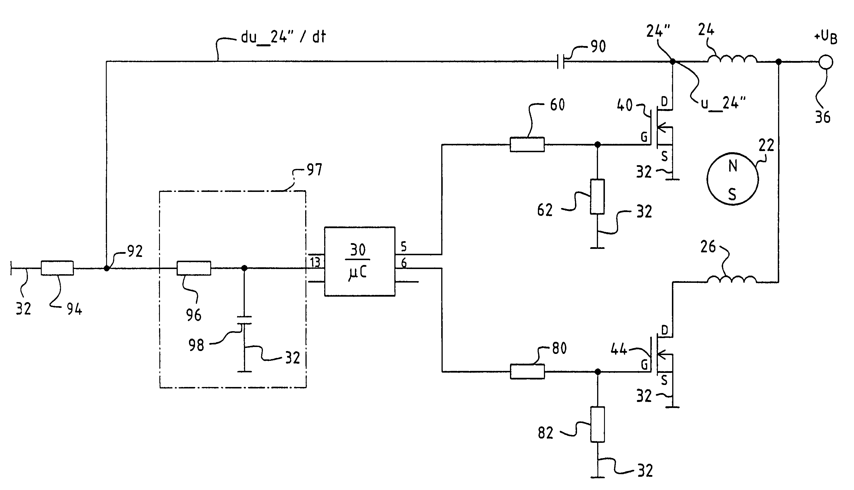
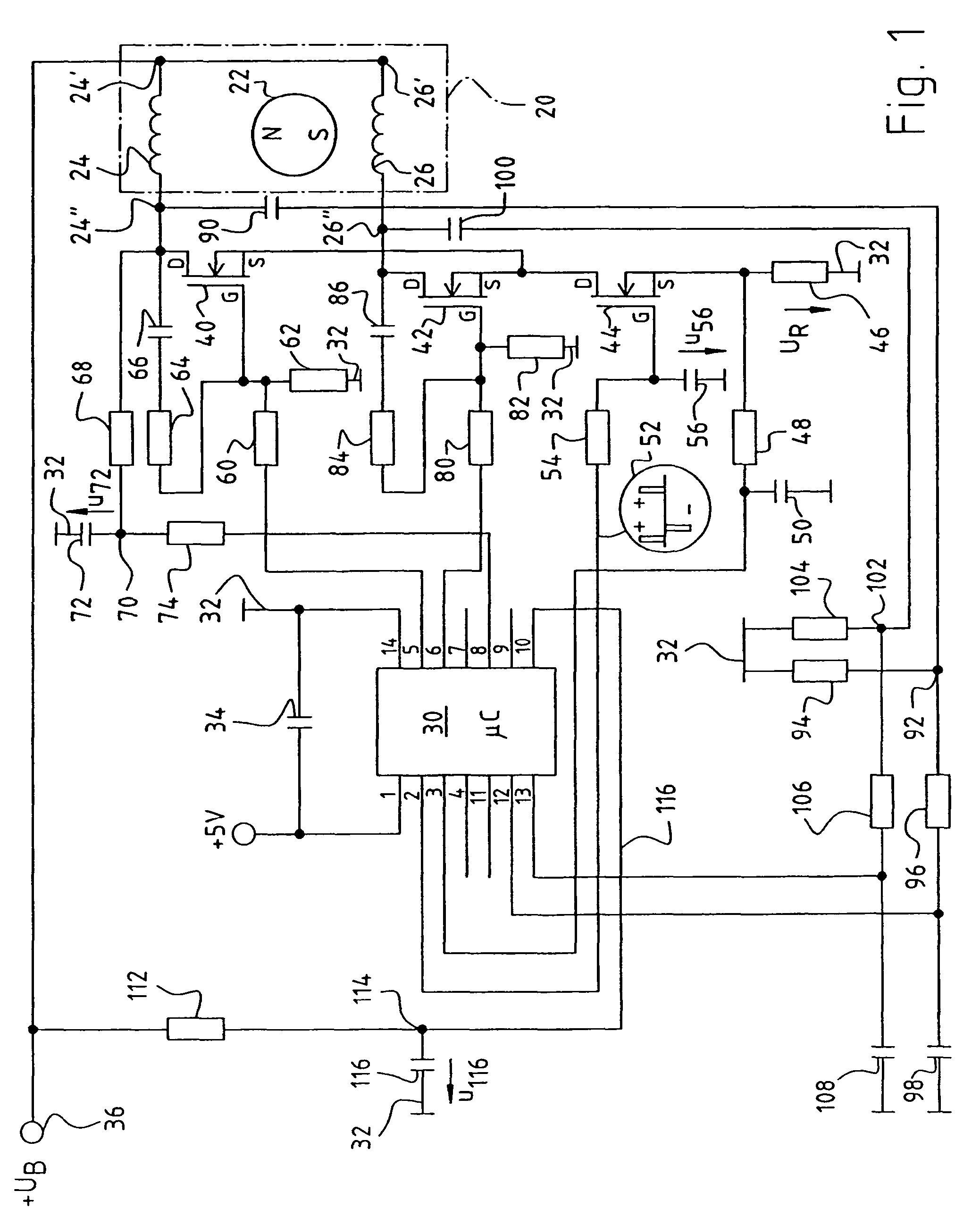
[0029]FIG. 1 shows a circuit for operating a so-called two-pulse electronically commutated motor 20 that has a permanent-magnet rotor 22 and a stator winding that is depicted here having two phases 24, 26, which are usually magnetically coupled to one another via the iron of the stator lamination stack (not depicted). A motor of this kind is called “two-pulse” because for each rotor rotation of 360° el., two stator current pulses flow in stator winding 24, 26. In many cases the stator winding can also have only one phase, and then a current pulse flows in it in the one direction during one rotation through 180° el., and a current pulse flows in the opposite direction during the subsequent rotation through 180° el. There are many designs for these motors, which are produced in enormous quantities. A typical example is shown in the Müller patents, DE 23 46 380-C2 and corresponding U.S. Pat. No. 4,119,895. Such motors are often implemented as so-called “claw pole” motors, the claw pole...


PUM


Abstract

An electronically commutated motor (ECM) often employs a Hall sensor for reliable operation. Even when a Hall sensor is omitted from a motor having a plurality of stator winding phases (24, 26) and a permanent-magnet rotor (22), one can reliably detect direction of rotation of the rotor by the steps of: (a) differentiating a voltage profile obtained by sampling either (1) induced voltage in a presently currentless phase winding or (2) voltage drop at a transistor, through which current is flowing to a presently energized phase winding, and (b) using such a differentiated signal (du—24″ / dt, du—26″ / dt) to control current flow in an associated phase winding. In this manner, one obtains reliable commutation, even if the motor is spatially separated from its commutation electronics.

Description

CROSS-REFERENCE[0001]This application claims priority from my German applications DE 10 2004 024 639.4 filed 12 MAY 2004 and DE 10 2005 007 905.9 filed 14 FEB. 2005, the entire contents of which are hereby incorporated by reference.FIELD OF THE INVENTION[0002]The invention relates to a method for sensorless operation of an electronically commutated motor (ECM), and a motor for carrying out such a method. Such a motor can have a single phase, or preferably a plurality of phases.BACKGROUND[0003]A preferred application of the invention is in “double-phase” motors. This may be explained as follows: because handy abbreviations are always desirable in engineering, and a differentiation in terms of “two-pulse” and “two-phase” is too complex for normal commerce, the generic term “double-phase motors” is usually used for such motors, regardless of whether such a motor has one or two phases.[0004]Because, for example, a two-pulse motor receives two stator current pulses (which in some circums...

Claims


Application Information

Patent Timeline
Patent Type & Authority Patents(United States)
IPC IPC(8): H02P1/04H02P6/18H02P9/14H02P9/18
CPCH02P6/182H02P9/14H02P9/18
Inventor DORNHOF, KONSTANTIN
Owner ELEKTROSIL SYST DER ELEKTRONIK
Why Eureka
Try Eureka