Method for commutating an electronically commutated motor and motor for carrying out said method

Inactive Publication Date: 2005-04-21
EBM PAPST ST GEORGEN & -
View PDF8 Cites 2 Cited by
  • Summary
  • Abstract
  • Description
  • Claims
  • Application Information

AI Technical Summary

Benefits of technology

[0007] A comparator is thus associated with each MOSFET of the bridge. When one of these MOSFETs is to be switched off, this occurs directly by way of its comparator. When one of these MOSFETs is to be switched on, the associated comparator then monitors the gate potential of the MOSFET that is to be switched off, i.e., in practice, its source-gate voltage. A reliable signal is thereby obtained as to when that MOSF

Problems solved by technology

A prerequisite for this, however, is that a microprocessor be used, and this is too expensive for many applications.
The current off-time of, for example, 50 μs must furthermore be made so long that is sufficie

Method used


Image

  • Method for commutating an electronically commutated motor and motor for carrying out said method
  • Method for commutating an electronically commutated motor and motor for carrying out said method
  • Method for commutating an electronically commutated motor and motor for carrying out said method

Examples


Example

[0010]FIG. 1 is a circuit diagram of a preferred embodiment of an electronically commutated motor for carrying out a method according to the present invention;

[0011]FIG. 2 is a diagram showing pulse sequences u1 and u2, to explain FIG. 1; and

[0012]FIG. 3 is a circuit diagram to explain, by way of example, the generation of two opposite-phase rotor position signals u1, u2, the amplitudes of which depend on the operating voltage UB of the motor.

DETAILED DESCRIPTION

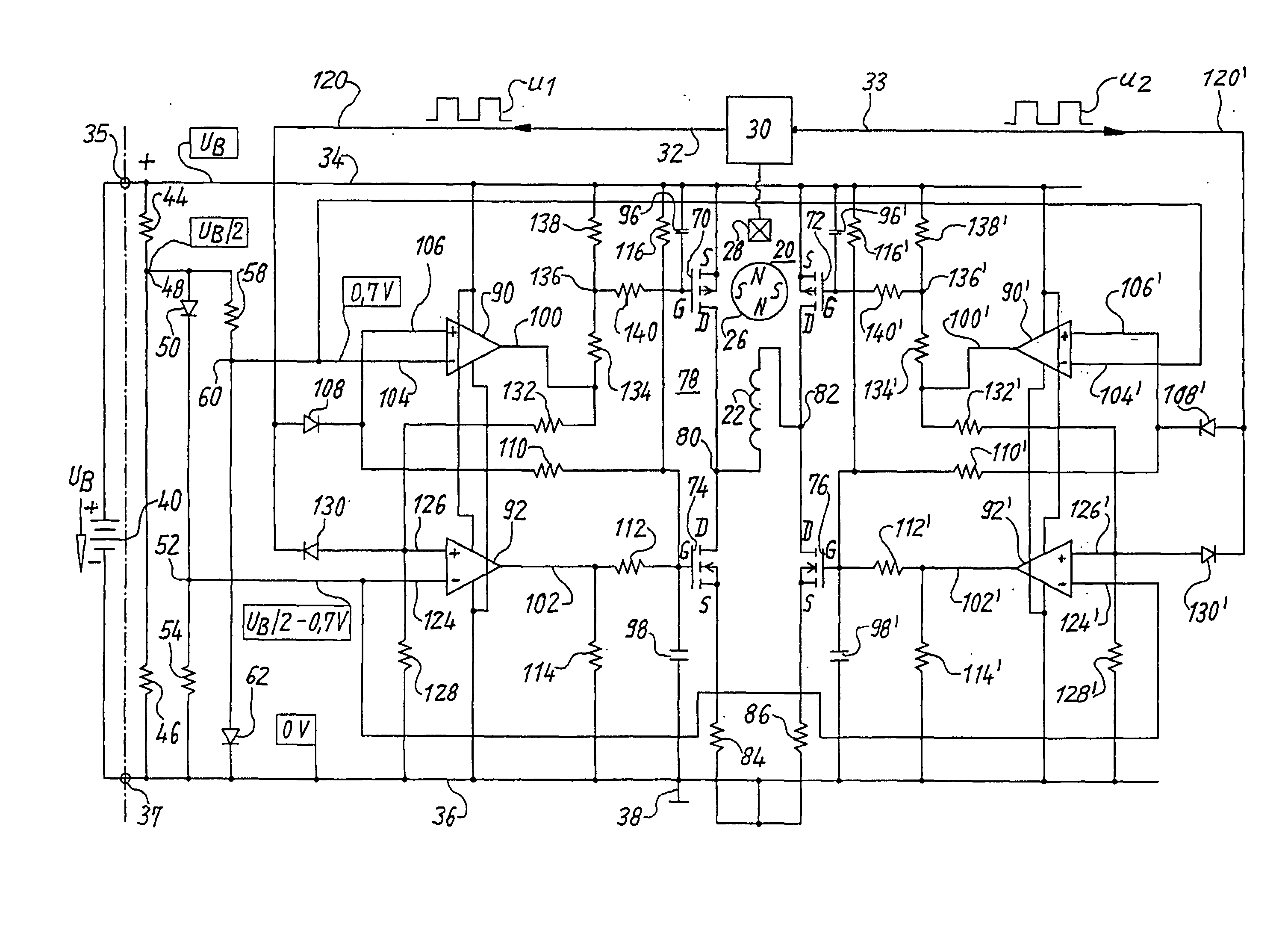
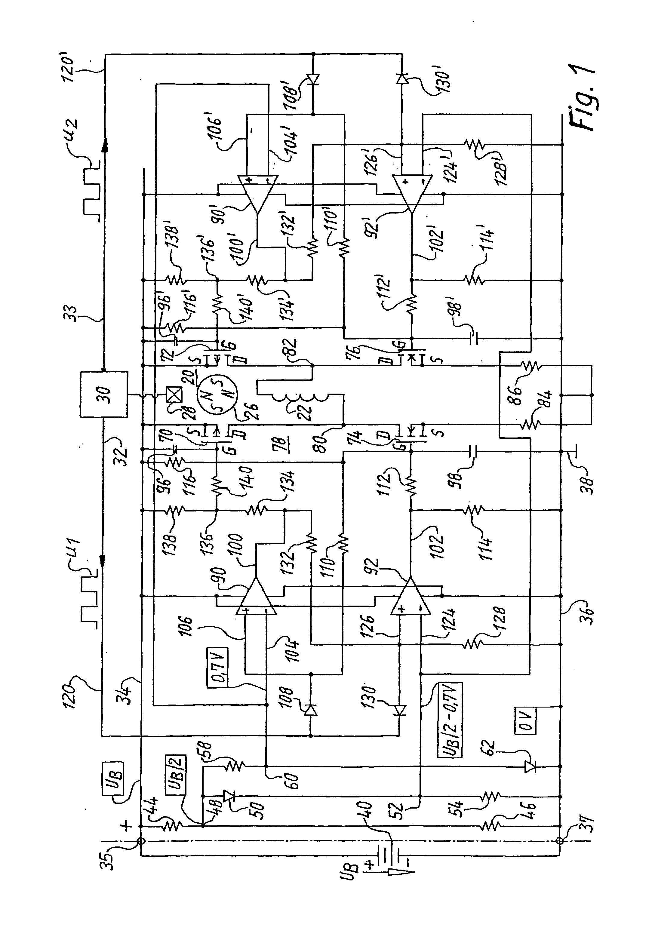
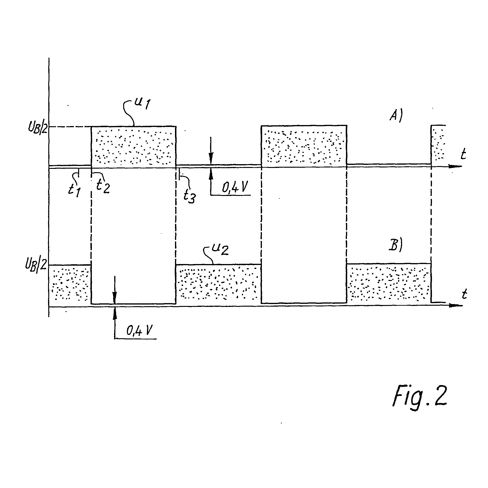
[0013]FIG. 1 shows, for explanation of the invention, a single-phase two-pulse electronically commutated motor 20 having a single stator winding phase 22, also having a permanent-magnet rotor 26 that is depicted as a four-pole rotor, and having a Hall generator 28 whose output signal is fed to an arrangement 30 having an output 32 and an output 33 antivalent thereto. In arrangement 30, the output signal of Hall generator 28 is converted into two square-wave signals u1 and u2, which are depicted in FIG. 2 and proceed in o...


PUM


Abstract

An improved method of commutating an electronically commutated motor (20) is disclosed. The motor has a positive (34) and a negative connecting lead (36), a stator having at least one winding phase (22), a permanent-magnet rotor (26), a rotor-position sensor (28) for producing a rotor position signal (u1, u2), and a full bridge circuit (78), comprising a pair of Metal Oxide Semiconductor Field Effect Transistors (MOSFETs) coupled to each end of each winding phase (22). In order to prevent current shoot-through and prolong the service life of the MOSFETs, without employing a microprocessor, a respective-comparator (90, 90′, 92, 92′) is coupled to the gate of each MOSFET, in order to assure that the MOSFET is switched ON and OFF at an optimum time.

Description

[0001] This application is a § 371 of PCT / EP03 / 00834, filed 28 JAN. 2003.FIELD OF THE INVENTION [0002] The invention concerns a method for commutating an electronically commutated motor, and a motor for carrying out such a method. BACKGROUND [0003] Electronically commutated motors operate with a stator winding that has a small number of phases. The motors principally used have one, two, or three phases. These phases can have power supplied to them in different ways depending on the type of electronics; supplying power via a full bridge circuit offers particular advantages. [0004] With a full bridge circuit, steps must be taken to ensure that a short circuit does not occur in the full bridge. There are numerous circuits for this, for example the circuit according to U.S. Pat. No. 4,376,261, von der Heide, et al., which is based on the principle of creating a small gap between two control pulses. When the full bridge is controlled via a microprocessor (μP), corresponding current off-t...

Claims


Application Information

Patent Timeline
IPC IPC(8): H02P6/15
CPCH02P6/142H02P6/15
Inventor BERROTH, HANSJORG
Owner EBM PAPST ST GEORGEN & -
Why Eureka
Try Eureka