
Solid oxide fuel cell

Active Publication Date: 2013-08-08
MIM CERAMICS
View PDF1 Cites 0 Cited by
  • Summary
  • Abstract
  • Description
  • Claims
  • Application Information

AI Technical Summary

Benefits of technology

The solid oxide fuel cell has several technical effects. Firstly, it does not require additional structures between cells, which increases power output per unit volume. Secondly, it has parallel air and fuel flow paths in the support body block, reducing the thickness of the electrolyte layer and increasing power generation efficiency. Thirdly, the number of stacks can be adjusted to adjust the area where air and fuel react, without changing cell shape, resulting in constant power generation efficiency regardless of low operating temperature. Fourthly, it has a self-supporting structure that makes it easy to manufacture. Lastly, it has a shorter distance from the power generation part to the electricity collecting plate, reducing electric resistance and increasing power generation efficiency.

Problems solved by technology

Thus, the cap has a structure substantially hard to manufacture.
For that reason, there is a problem in that the power generation area per unit volume is reduced if the cap is arranged between the unit cells adjoining each other.
In this case, however, the moving route of electrons becomes longer and the power generation efficiency grows lower.
This poses a problem in that it is difficult to increase the power generation capacity.
Moreover, a difficulty is involved in forming long channels in an electrolyte support body.
It is also highly likely that defects are generated in the process of forming the long channels.
In addition, there is a need to increase the size of the cap which is hard to manufacture.
In general, the electricity collecting plates are made of an expensive metallic material.
This poses a problem of increasing the moving distance of electrons.

Method used


Image

  • Solid oxide fuel cell
  • Solid oxide fuel cell
  • Solid oxide fuel cell

Examples


Embodiment Construction

[0038]A solid oxide fuel cell according to one embodiment of the present invention will now be described in detail with reference to the accompanying drawings.

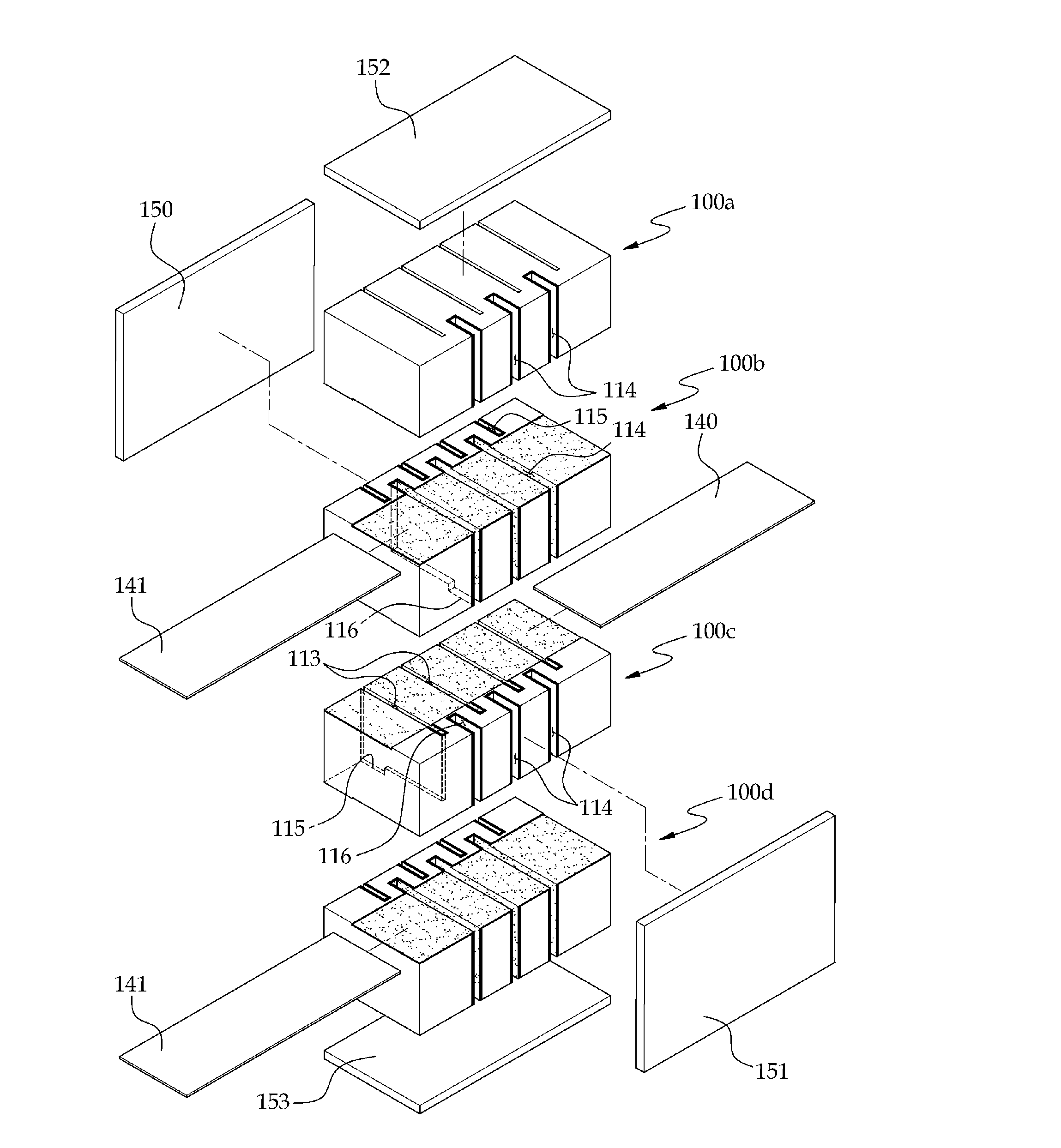
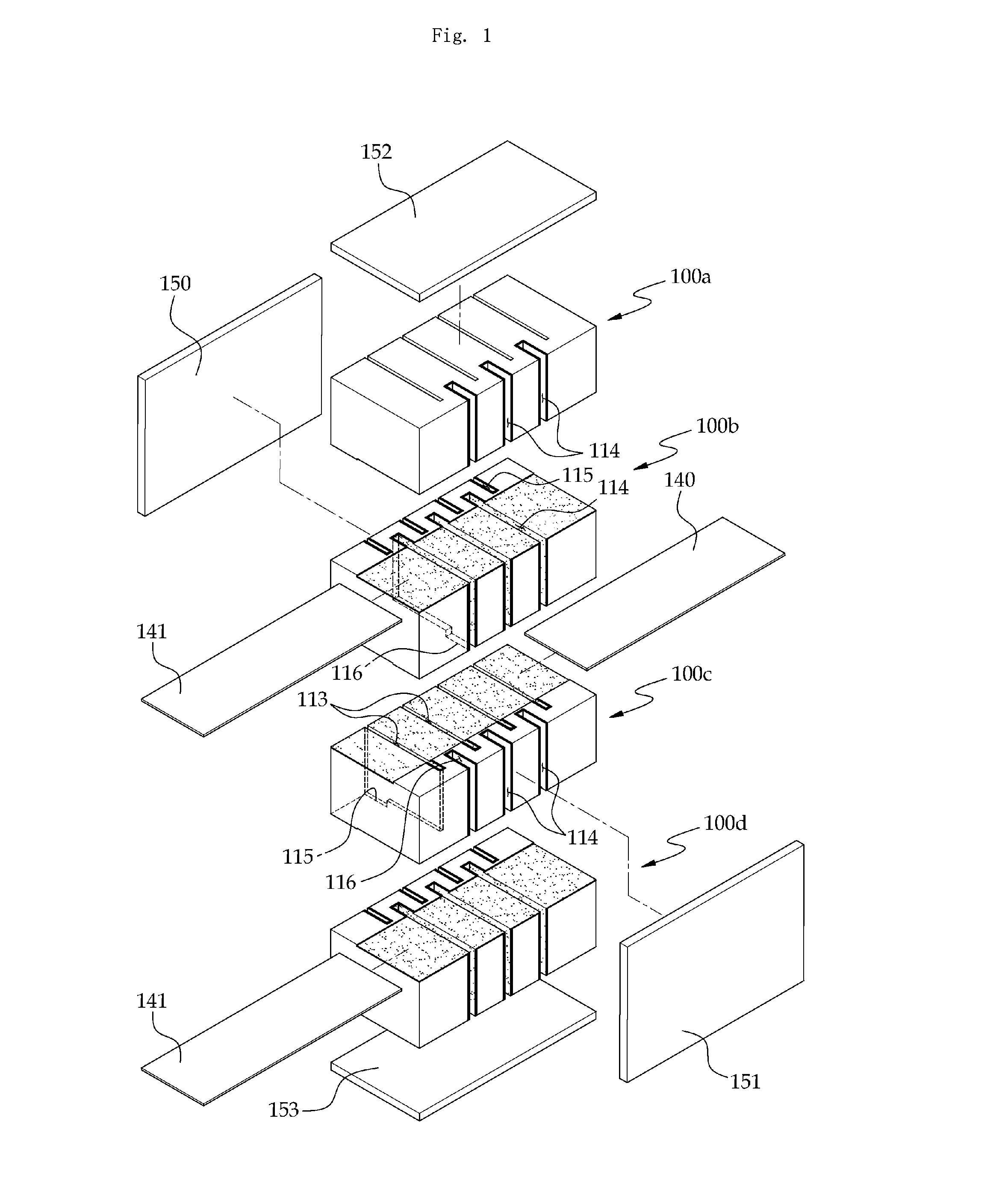
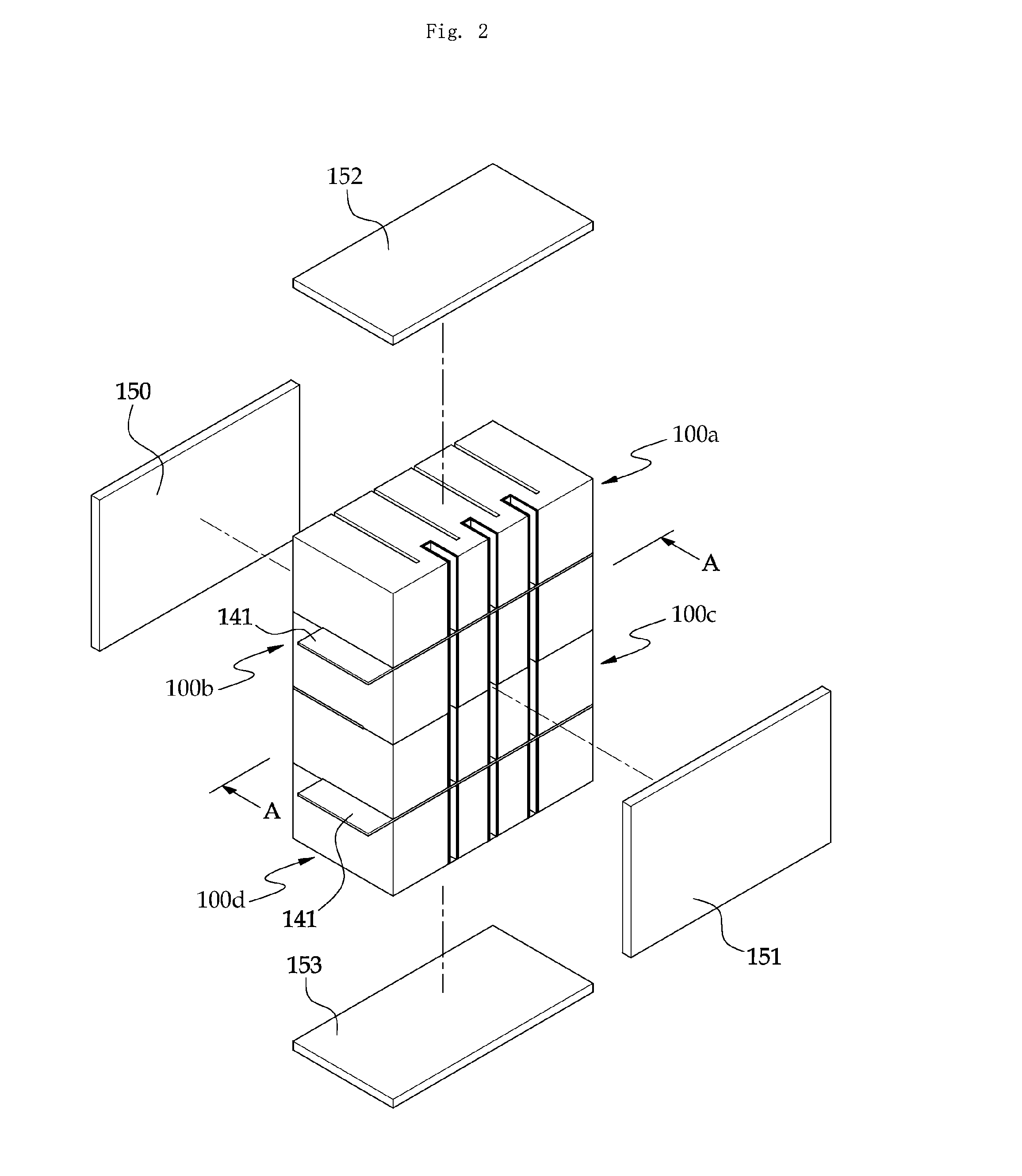
[0039]FIG. 1 is an exploded perspective view showing a solid oxide fuel cell according to one embodiment of the present invention. FIG. 2 is a perspective view illustrating a state that the unit cells of the solid oxide fuel cell shown in FIG. 1 are combined together. FIG. 3 is a perspective view showing one of the unit cells shown in FIG. 1. FIG. 4 is a section view of the solid oxide fuel cell taken along line A-A in FIG. 2.

[0040]Referring to FIGS. 1 and 2, the solid oxide fuel cell according to one embodiment of the present invention includes a plurality of unit cells 100a, 100b, 100c and 100d, a plurality of electricity collecting plates 140 and 141 and a pair of side plates 150 and 151.

[0041]Referring to FIGS. 3 and 4, each of the unit cells 100 includes a support body block 110, an air electrode 120, a fuel electrode 121...


PUM


Abstract

A solid oxide fuel cell includes unit cells, a first side plate and a second side plate respectively attached to opposite lateral surfaces of the unit cells, and a first electricity collector and a second electricity collector arranged between the unit cells. Each of the unit cells includes a support body block. The support body block includes a first surface, a second surface parallel to the first surface, a plurality of first channels and a plurality of second channels existing between the first channels. Each of the unit cells further includes air electrodes formed on inner surfaces of the first channels, fuel electrodes formed on inner surfaces of the second channels, a first electricity collecting layer formed on the first surface and electrically connected to the air electrodes and a second electricity collecting layer formed on the second surface and electrically connected to the fuel electrodes.

Description

FIELD OF THE INVENTION[0001]The present invention relates to a solid oxide fuel cell and, more particularly, to a highly-efficient solid oxide fuel cell having an increased electrode area per unit volume.BACKGROUND OF THE INVENTION[0002]A fuel cell is a device for converting a change in free energy caused by oxidation reaction of fuel to electric energy. As examples of the fuel cell, there have been developed a phosphate fuel cell, a polymer electrolyte fuel cell, a molten carbonate fuel cell and a solid oxide fuel cell.[0003]The solid oxide fuel cell is capable of generating electric energy at a high temperature of 600° C. to 1,000° C. Therefore, the solid oxide fuel cell enjoys highest energy conversion efficiency among the fuel cells developed thus far. Thanks to the high energy conversion efficiency, the solid oxide fuel cell, if practically available, can become a substitute for the existing energy converters. If hydrogen is used as the fuel of the solid oxide fuel cell, it is ...

Claims


Application Information

Patent Timeline
IPC IPC(8): H01M8/02
CPCY02E60/521Y02E60/525H01M8/12Y02E60/50H01M8/02H01M8/0258H01M8/24H01M8/2425H01M2008/1293H01M8/2435H01M8/2432H01M8/2457H01M8/0263H01M8/026
Inventor KIM, YOUNG JUNG
Owner MIM CERAMICS
Learn More