Turbocharger system having an air-cooled solenoid valve

Active Publication Date: 2016-08-02
FORD GLOBAL TECH LLC
View PDF9 Cites 1 Cited by
  • Summary
  • Abstract
  • Description
  • Claims
  • Application Information

AI Technical Summary

Benefits of technology

[0003]Boosting device, such as turbochargers and superchargers, may be used in engines. Turbochargers may i

Problems solved by technology

However, due to the proximity of the turbine to the combustion chamber, the turbine and surrounding components may experience elevated temperatures.
Consequently, the turbine and surrounding components may experience thermal degradation, decreasing component longevity.
For example, wastegates may become inoperable during such over-temperature conditions.
Wastegate actuators may be particularly susceptible to elevated temperatures due to the characte

Method used


Image

  • Turbocharger system having an air-cooled solenoid valve
  • Turbocharger system having an air-cooled solenoid valve
  • Turbocharger system having an air-cooled solenoid valve

Examples


Embodiment Construction

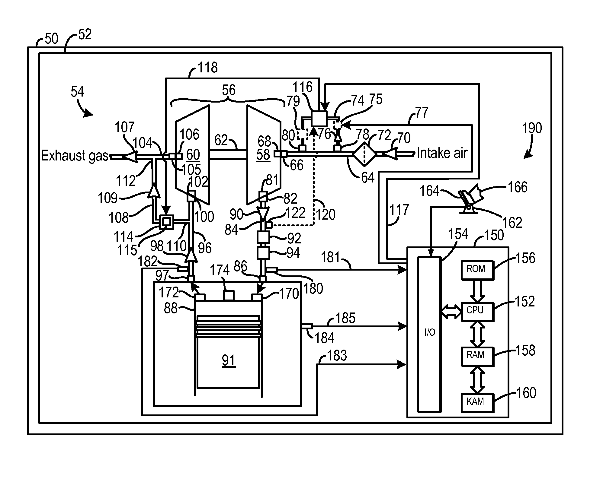
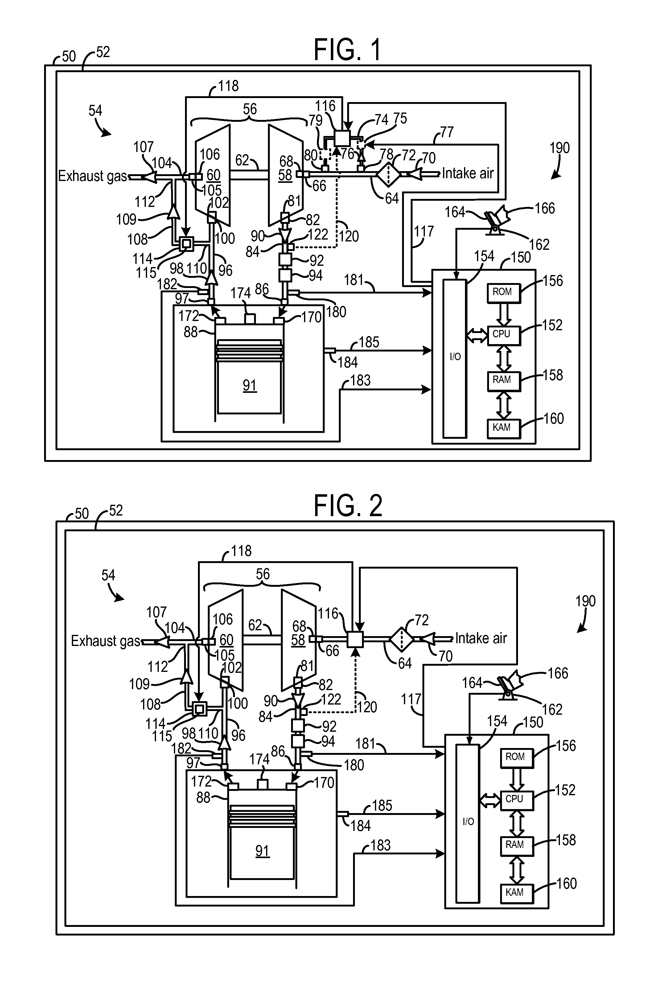
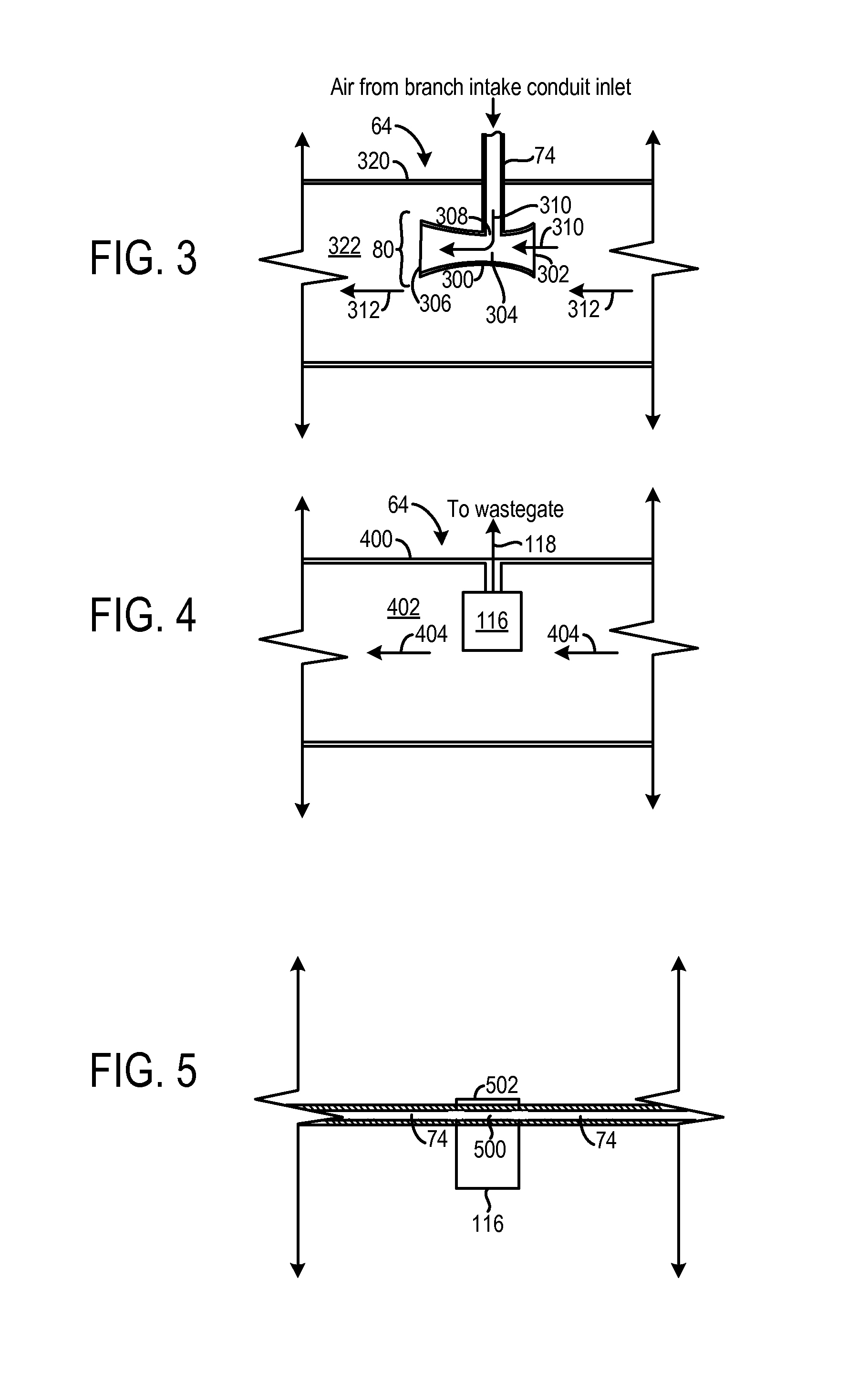
[0019]A turbocharger system having an air-cooled wastegate actuator and / or air-cooled solenoid valve is described herein. The wastegate actuator converts electrical control signals received from a control system into mechanical actuation. The mechanical actuation is translated from the wastegate actuator to the wastegate valve in the turbine bypass conduit. Intake air may be routed to the wastegate actuator to cool the actuator, and then be routed back to the intake system. In one example, un-compressed intake air may be routed to the wastegate actuator to cool the actuator and then returned back to the compressor inlet. In this way, exhaust heat transferred to the wastegate actuator may be dissipated in the cooling air. Further, when using a charge-air cooling downstream of the compressor, the warmed intake air can then be cooled before being ingested in the engine.

[0020]Thus, in one embodiment, the air-cooled wastegate actuator receives intake air from the intake system to reduce ...


PUM


Abstract

A turbocharger system is provided. The turbocharger system includes a turbine positioned downstream of a combustion chamber and a turbine bypass conduit in fluidic communication with a turbine inlet and a turbine outlet. The turbocharger system further includes a wastegate positioned in the turbine bypass conduit, a wastegate actuator coupled to the wastegate adjusting a position of the wastegate, and an air-cooled solenoid valve coupled to wastegate actuator adjusting a position of the wastegate actuator, the air-cooled solenoid valve receiving cooling airflow from an intake conduit positioned upstream of a compressor mechanically coupled to the turbine.

Description

CROSS REFERENCE TO RELATED APPLICATIONS[0001]The present application is a continuation-in-part of U.S. patent application Ser. No. 13 / 588,593, filed on Aug. 17, 2012, the entire contents of which are hereby incorporated by reference for all purposes.FIELD[0002]The present disclosure relates to an air-cooled solenoid valve in a turbocharger system in a vehicle.BACKGROUND / SUMMARY[0003]Boosting device, such as turbochargers and superchargers, may be used in engines. Turbochargers may increase the power output of the engine for a given displacement as compared to a naturally aspirated engine.[0004]It may be desirable to decrease the flow path between the turbine in the turbocharger and the combustion chambers by positioning the turbine close to the exhaust ports of the cylinders. Such positioning decreases losses in the exhaust gas flow, thereby enabling the speed of the turbine to increase. The increased turbine speed increases the amount of compression provided by the compressor. As a...

Claims


Application Information

Patent Timeline
IPC IPC(8): F02B33/44F02B33/00F02B37/16F02B37/18
CPCF02B33/00F02B37/164F02B37/186Y02T10/144F02B33/40F02B37/16F02M35/10157F02M35/10209F02M35/10268Y02T10/12
Inventor MATTHEWS, PATRICK
Owner FORD GLOBAL TECH LLC
Why Eureka
Try Eureka