Miniature high-temperature and high-pressure electric rotary valve

A high-voltage, high-temperature technology, applied in the field of miniature high-temperature and high-pressure rotary valves, can solve the problems of unbalanced hydraulic pressure of the rotary valve core, aggravated friction and wear of the valve core and seat, and large operating force, so as to expand the working pressure range, The effect of compact structure and reliable sealing performance

Inactive Publication Date: 2016-02-24
PETROLEUM ENG TECH RES INST OF JIANGHAN OILFIELD BRANCH OF
View PDF5 Cites 2 Cited by
  • Summary
  • Abstract
  • Description
  • Claims
  • Application Information

AI Technical Summary

Problems solved by technology

However, no matter what kind of rotary valve is sealed, the hydraulic pressure on the rotary valve core cannot be balanced. Due to the large sealing surface, when used in medium and high pressure conditions, the valve core has to bear large hydraulic pressure. Undoubtedly, it will increase the friction and wear of the valve core and seat, and at the same time require greater operating force

Method used


Image

  • Miniature high-temperature and high-pressure electric rotary valve
  • Miniature high-temperature and high-pressure electric rotary valve
  • Miniature high-temperature and high-pressure electric rotary valve

Examples


Embodiment Construction

[0026] The present invention will be further described below in conjunction with accompanying drawing.

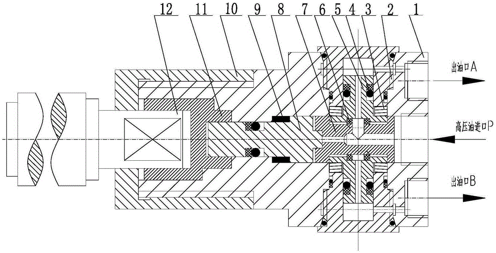
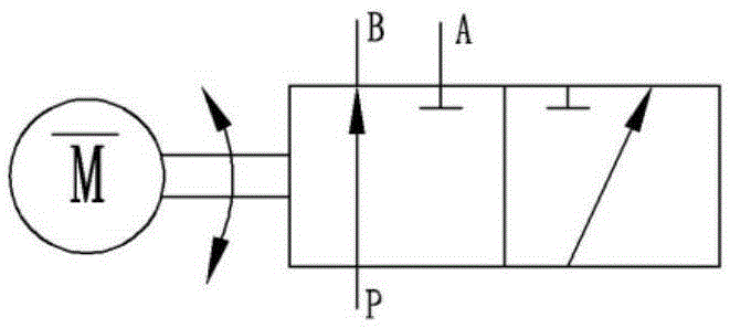
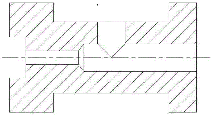
[0027] Such as Figure 1-4 As shown, the present embodiment provides a miniature high-temperature, high-pressure electric rotary valve, including a cylindrical valve body 12, a valve core hole is provided in the valve body 12, and a rotatable cylindrical valve core 6 is arranged in the valve core hole. One end of the valve core 6 is sequentially connected with a valve stem 7 and a limit connection shaft 10, the limit connection shaft 10 is connected with the motor output shaft 11, and the end cover 9 is screwed on the left end of the valve body 12, and the valve body 12 There are valve seat holes arranged symmetrically on both sides of the valve core hole, and the valve seat holes are vertically arranged with the valve core hole. A floating valve seat 4 is arranged in the valve seat hole, and rings are symmetrically opened on the outer circumference of the valve core 6. Th...


PUM


Abstract

The invention discloses a miniature high-temperature and high-pressure electric rotary valve. The miniature high-temperature and high-pressure electric rotary valve comprises a cylindrical valve body, a valve core, a valve rod and a limiting connecting shaft, wherein valve seat holes are symmetrically formed in both sides of a valve core hole in the valve body, floating valve seats are arranged in the valve seat holes, the floating valve seats are matched with the valve core through curved surfaces, a port P, a port A and a port B are formed in the right end of the valve body, the three oil ports are all axially formed and are positioned in the same end surface, a part, which is communicated with the port P, of the valve core forms a cavity P, parts, which are respectively communicated with the port A and the port B, of the two floating valve seats form a cavity A and a cavity B, and the valve core is driven to reverse leftwards or rightwards by a motor, so that the port A is communicated with the port A or the port B to form a two-position three-way reversing valve. The miniature high-temperature and high-pressure electric rotary valve has the advantages of small size, compact structure and reliable sealing performance and is compatible with the small installation space of an annular pipeline, the reliable reversing of an oil system can be guaranteed, and the miniature high-temperature and high-pressure electric rotary valve can be applied in high-temperature and high-pressure severe environments such as power plants, petroleum and natural gas exploitation and the like.

Description

technical field [0001] The invention relates to a fluid control valve, in particular to a miniature high-temperature and high-pressure rotary valve, which can be used for fluid control in high-temperature and high-pressure environments such as power plants and oil and gas exploitation. Background technique [0002] In high-temperature and high-pressure occasions such as nuclear power plants, crude oil extraction, and natural gas extraction, the commonly used reversing valves include ball valves, slide valves, cone valves, and plate valves. Cone valves and flat valves need to realize multi-position and multi-way functions, not only the structure is more complicated, but also the external dimensions are large, so it is difficult to take into account the compact structure and integrated functions at the same time; the ball valve relies on the tight fit of the valve ball and the valve seat to achieve reliable sealing , when fully open or fully closed, the sealing surface of the ...

Claims


Application Information

Patent Timeline
Patent Type & Authority Applications(China)
IPC IPC(8): F16K5/04F16K5/08F16K5/18F16K11/085F16K31/04
CPCF16K5/04F16K5/0242F16K5/08F16K5/181F16K11/085F16K31/041
Inventor 樊丽丽汪团员韩明兴马文斌贺冬赵立帅
Owner PETROLEUM ENG TECH RES INST OF JIANGHAN OILFIELD BRANCH OF
Why Eureka
Try Eureka