Rolling brush regulating device for snow sweeper

A technology of snow removal vehicles and rolling brushes, which is applied in snow surface cleaning, construction, cleaning methods, etc. It can solve the problems of difficult control of contact pressure, easy wear of rolling brushes, and incomplete snow removal, so as to achieve the goal of not being easy to wear and ensuring accuracy , The effect of reliable commutation

Pending Publication Date: 2017-12-19
SINOTRUK LIUZHOU YUNLI SPECIAL PURPOSE VEHICLES
View PDF11 Cites 2 Cited by
  • Summary
  • Abstract
  • Description
  • Claims
  • Application Information

AI Technical Summary

Problems solved by technology

[0003] The invention provides a rolling brush pressing down control device of a snow removal vehicle, which can solve the problem that the contact pressure between the rolling brush of the existing snow removal vehicle and the ground is difficult to be controlled within the optimal range, which causes the rolling brush to be easily worn or snow accumulated Clean up incomplete problems

Method used


Image

  • Rolling brush regulating device for snow sweeper
  • Rolling brush regulating device for snow sweeper
  • Rolling brush regulating device for snow sweeper

Examples


Embodiment 1

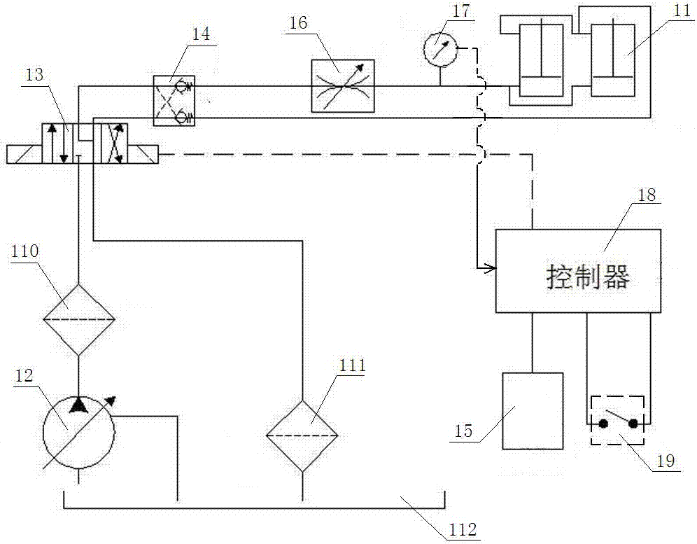
[0020] figure 2 The shown snow removal vehicle rolling brush down pressure control device includes a lifting cylinder 11 that drives the roll brush down and a hydraulic pump 12 that provides pressure oil for the lifting cylinder 11. One-way hydraulic pressure is sequentially arranged between the lifting cylinder 11 and the hydraulic pump 12 Lock 14 and solenoid reversing valve 13, solenoid reversing valve 13 is a three-position four-way valve; there is an adjustable flow valve 16 between the rodless cavity of the lifting cylinder 11 and the one-way hydraulic lock 14, and the lifting cylinder 11 has no rod A pressure sensor 17 is provided between the cavity and the adjustable flow valve 16; a first filter element 110 is provided between the electromagnetic reversing valve 13 and the hydraulic pump 12, and a second filter element 111 is provided between the electromagnetic reversing valve 13 and the oil tank 112; pressure The sensor 17 is connected to the electric control end of ...

Embodiment 2

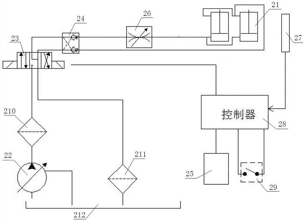
[0023] image 3 The shown snow removal vehicle rolling brush downward pressure control device includes a lifting oil cylinder 21 that drives the rolling brush downward and a hydraulic pump 22 that provides pressure oil for the lifting oil cylinder 21. One-way hydraulic pressure is sequentially arranged between the lifting oil cylinder 21 and the hydraulic pump 22. The lock 24 and the electromagnetic reversing valve 23, the electromagnetic reversing valve 23 is a three-position four-way valve; an adjustable flow valve 26 is arranged between the rodless cavity of the lifting cylinder 21 and the one-way hydraulic lock 24; the electromagnetic reversing valve 23 and A first filter element 210 is provided between the hydraulic pump 22, and a second filter element 211 is provided between the electromagnetic reversing valve 23 and the oil tank 212; a displacement sensor 27 is provided at the piston rod corresponding to the lifting cylinder 21; the displacement sensor 27 passes through t...


PUM


Abstract

The invention discloses a pressing control device for a rolling brush of a snow sweeper and belongs to the technical field of engineering machinery. The device comprises a lifting cylinder and a hydraulic pump, wherein the lifting cylinder is used for driving the rolling brush to press down; the hydraulic pump is used for supplying pressure oil to the lifting cylinder; a solenoid directional valve is arranged between the lifting cylinder and the hydraulic pump; a sensor used for sensing the abrasion of the rolling brush is also arranged on the device; the sensor is connected with an electric control end of the solenoid directional valve through a controller; an automatic pressing switch for the rolling brush and a snow sweeping operation handle are arranged at a control end of the controller. The pressing control device is capable of solving the problem of easy abrasion of the rolling brush or incomplete snow sweeping caused by the difficulty in controlling the contact pressure between the rolling brush of the snow sweeper and the ground within the optimal scope.

Description

Technical field [0001] The invention relates to the technical field of engineering machinery manufacturing, in particular to a rolling brush downward pressure control device for a snow removal vehicle. Background technique [0002] The rolling brush down pressure control device of the snow removal vehicle is a device that controls the rolling brush set on the snow removal vehicle to press against the ground, so that the rolling brush contacts the ground and generates a certain contact pressure to clean the snow on the road surface; figure 1 The shown snow removal vehicle rolling brush downward pressure control device includes a lifting oil cylinder 01 that drives the rolling brush downward and a hydraulic pump 02 that provides pressure oil for the lifting oil cylinder 01. One-way hydraulic pressure is sequentially arranged between the lifting oil cylinder 01 and the hydraulic pump 02. Lock 04 and solenoid reversing valve 03. The electric control end of solenoid reversing valve 03 ...

Claims


Application Information

Patent Timeline
Patent Type & Authority Applications(China)
IPC IPC(8): E01H5/09
CPCE01H5/092
Inventor 莫玉振唐毅林李旭俊蒋春玲薛志敏吴亮熹邱翰健陈泳松杨涵智韦剑锋
Owner SINOTRUK LIUZHOU YUNLI SPECIAL PURPOSE VEHICLES
Why Eureka
Try Eureka