
Three-dimensional object tracking using distributed thin-client cameras

a thin-client camera and three-dimensional object technology, applied in the field of three-dimensional object identification and tracking systems, can solve the problems of unreliable object position estimation, aforementioned techniques fail to construct three-dimensional volumes of objects being tracked to provide a more reliable estimation, and aforementioned techniques often have difficulty in tracking multiple objects, so as to achieve efficient and reliable tracking of objects, easy to scale

Active Publication Date: 2011-11-15
DELL MARKETING CORP
View PDF14 Cites 36 Cited by
  • Summary
  • Abstract
  • Description
  • Claims
  • Application Information

AI Technical Summary

Benefits of technology

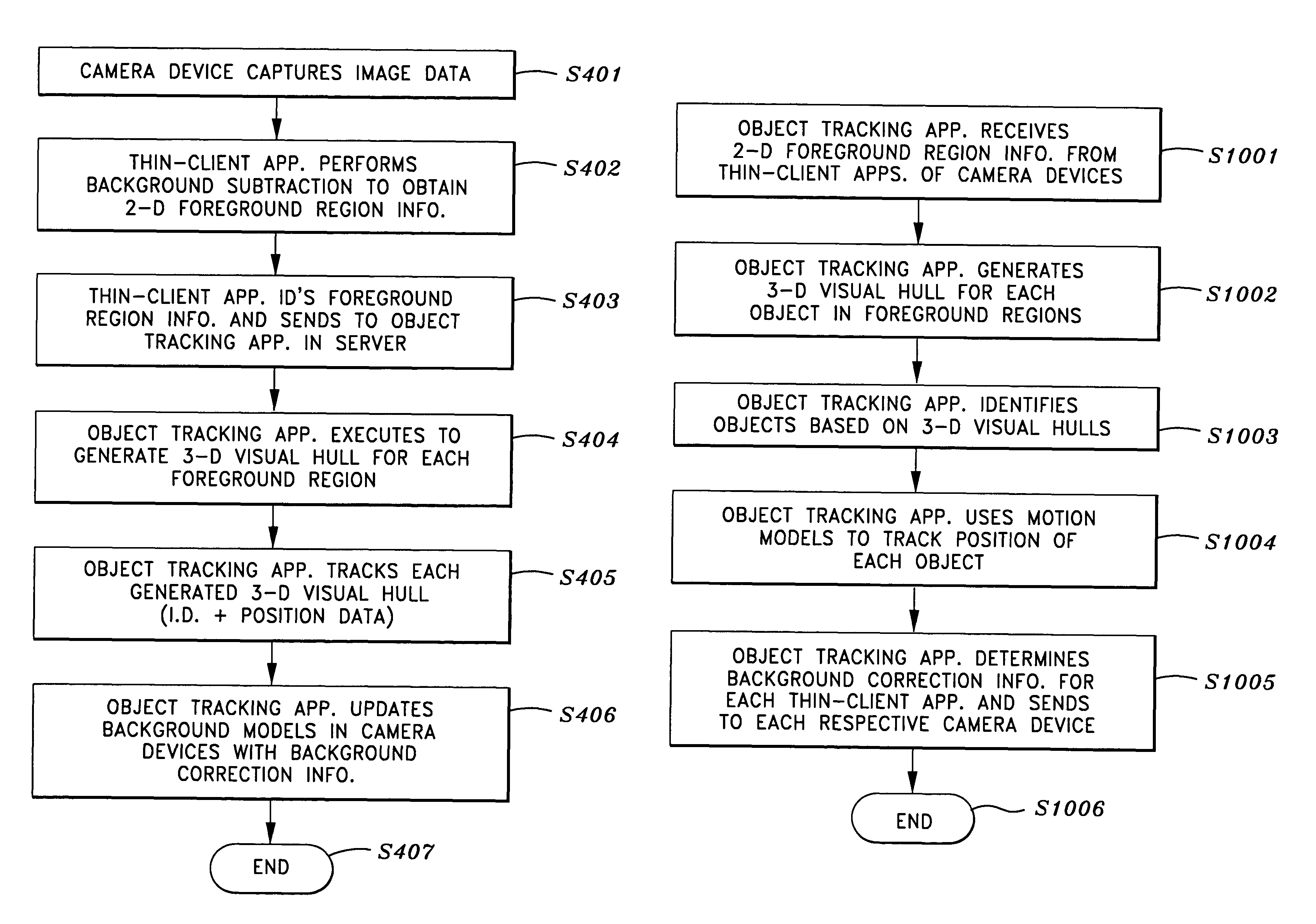
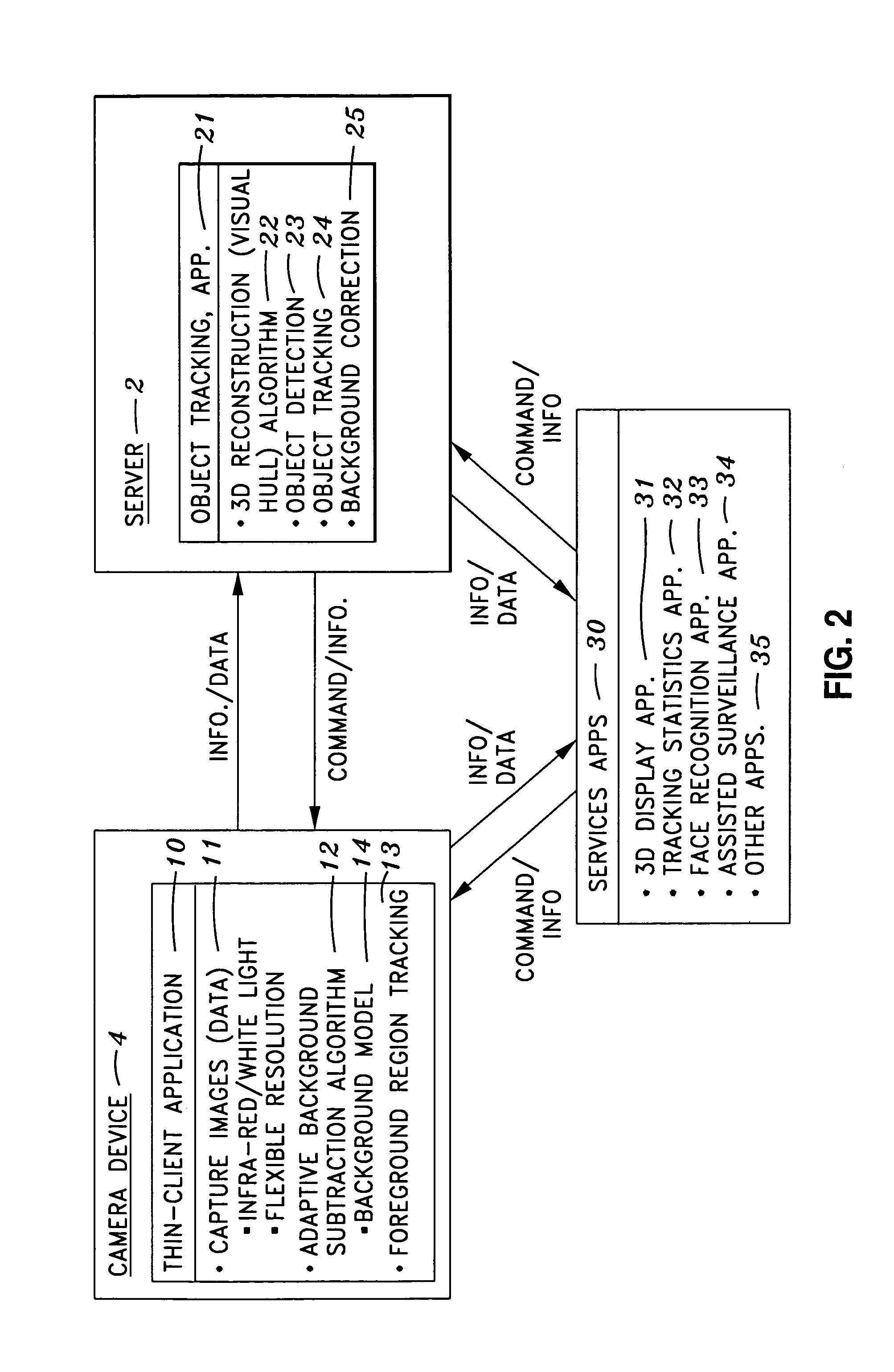
"The present invention provides an object tracking system that uses a distributed system of thin-client connected cameras and a server to efficiently and reliably track objects. The system uses a background subtraction algorithm to determine foreground regions and track objects in the foreground regions at the thin-client application and then generates a three-dimensional visual hull for each object detected by the cameras at the server level. The system is easily scalable and uses two-dimensional object tracking in the thin-clients to reduce the presence of phantom objects. The thin-client application is remotely controlled and synchronized by the object tracking application in the server, and sends the foreground region information to the server via a network environment. The server generates identification and position data for each three-dimensional visual hull and periodically updates the background model to provide more accurate separation of the foreground regions. Overall, the invention provides an efficient and reliable solution for identifying and tracking objects in a network environment."

Problems solved by technology

The foregoing known techniques suffer from the problem of either using only two-dimensional data in the first example, or using only three-dimensional centroid estimates in the second example, both of which are known to result in unreliable object position estimates.
In addition, both techniques fail to construct three-dimensional volumes of the objects being tracked to provide a more reliable estimation of the object size and movement relative to the background of the camera image.
The aforementioned techniques also often have difficulty when attempting to track multiple objects, especially when the objects are near each other.
Finally, the foregoing techniques are processing intensive because they use a central processor for performing all image processing and they are therefore limited in scalability.

Method used


Image

  • Three-dimensional object tracking using distributed thin-client cameras
  • Three-dimensional object tracking using distributed thin-client cameras
  • Three-dimensional object tracking using distributed thin-client cameras

Examples


Embodiment Construction

[0025]As mentioned above, the present invention is generally directed to a distributed system which includes multiple thin-client connected cameras that process image data at the thin-client and then send detected foreground image information to a server which then creates a three-dimensional visual hull representing each object based on the collective foreground image information obtained from the plurality of thin-clients.

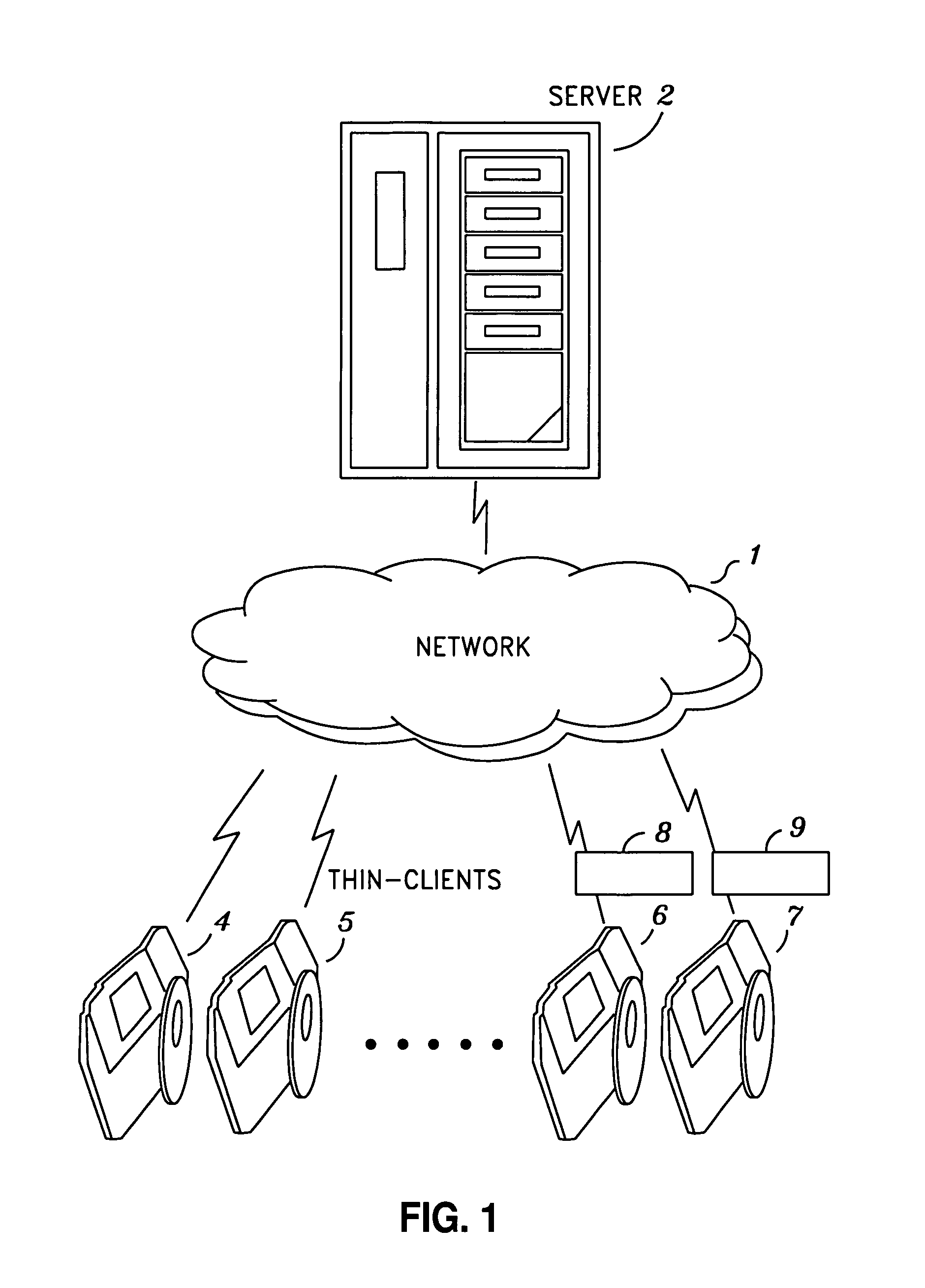
[0026]Turning the drawings, FIG. 1 presents a network environment in which the present invention may be practiced. As seen in FIG. 1, the object tracking system of the present invention includes server 2, network 1 and camera devices 4 to 7. Network 1 may be a wired or a wireless LAN or may be the internet. Various types of transport protocol can be used for communication between server 2 and camera devices 4 to 7 via network 1, such as TCP, HTTP, or a custom protocol. If desired, the communication can be performed in a secure manner by also using secure protocol...


PUM


Abstract

An object tracking system which includes a plurality of camera devices, each of which captures image data, a plurality of thin-client processors, each of which is connected to a respective camera device via a local connection, each thin-client processor hosting a thin-client application that processes the captured image data to obtain two-dimensional foreground region information by using a background subtraction algorithm, and a server hosting an object tracking application that receives the foreground region information from each thin-client processor via a network and generates a three-dimensional visual hull corresponding to each foreground region represented in the received foreground region information, wherein the object tracking application generates identification and position data corresponding to each three-dimensional visual hull. The thin-client application uses two-dimensional object tracking to identify each object in the foreground region information, and sends each object identity to the object tracking application with the foreground region information.

Description

BACKGROUND OF THE INVENTION[0001]1. Field of the Invention[0002]The present invention concerns a system for identifying and tracking three-dimensional objects by utilizing a distributed system of thin-clients connected to cameras and a server which creates a three-dimensional visual hull for the objects recorded by the cameras.[0003]2. Description of the Related Art[0004]Typically, object detection using cameras is performed by a single stereo-type camera which sends the image information to a central processor that performs two-dimensional filtering and uses object templates to determine the position of an object. Other known camera systems include the use of multiple cameras wherein the image data from each camera is sent to a central processor that determines foreground centroid coordinate information for each camera and then triangulates the position of each object based on the collective centroid coordinate information.[0005]The foregoing known techniques suffer from the proble...

Claims


Application Information

Patent Timeline
Patent Type & Authority Patents(United States)
IPC IPC(8): H04N5/225
CPCH04N5/232H04N23/661H04N23/61H04N23/63
Inventor BARRETO, DANIELSCHWEBKE, CURT
Owner DELL MARKETING CORP
Learn More