Rough road detection system used in an on-board diagnostic system

a detection system and diagnostic system technology, applied in the field of rough road detection system, can solve the problems of creating false positives (alpha errors) in the diagnostic components, inaccurate estimation of the frictional coefficient of the road surface, and misfire monitors are prone to false positives, so as to reduce false positive error determinations and reduce false positive errors

Active Publication Date: 2011-11-15
FORD GLOBAL TECH LLC
View PDF32 Cites 14 Cited by
  • Summary
  • Abstract
  • Description
  • Claims
  • Application Information

AI Technical Summary

Benefits of technology

[0005]According to yet another aspect, a method to reduce false positives from a diagnostic component in a vehicle traveling on a road is provided. The method comprises receiving input signals from wheel speed sensors; determining changes of the input signals using a high pass filter so that output signals from the high pass filter indicate a current magnitude of external roughness of the road surface; processing the output signals from the high pass filter using a rolling average filter so that a roughness level is determined over a predetermined time interval; comparing the output signals from the rolling average filter to a predetermined threshold; and disabling an error output of the diagnostic component if the roughness level has exceeded the predetermined threshold.
[0006]The use of a rough road detector (RRD) can reduce false errors from a diagnostic component. In the case where the diagnostic component is a misfire monitor, once the misfire monitor receives the RRD flag, a control system may instruct the misfire monitor to disable the misfire output, switch to an alternate calibration, or deactivate the misfire monitor while traveling over a rough road.

Problems solved by technology

However, the roughness of a road surface may create false positives (alpha errors) in the diagnostic components.
The misfire monitor can be prone to false positives under extreme road surface conditions.
In another example, the roughness of the road may result in an inaccurate estimation of a road surface frictional coefficient which is used to control four wheel driving and automatic braking.
Thus, some engine or vehicle control operations may not be accurately performed under a rough road condition.

Method used


Image

  • Rough road detection system used in an on-board diagnostic system
  • Rough road detection system used in an on-board diagnostic system
  • Rough road detection system used in an on-board diagnostic system

Examples


Embodiment Construction

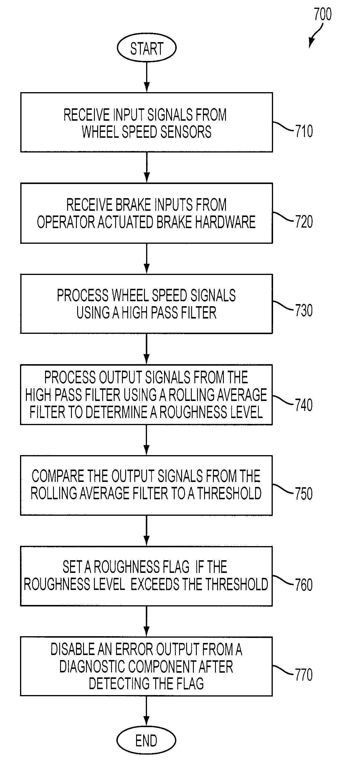
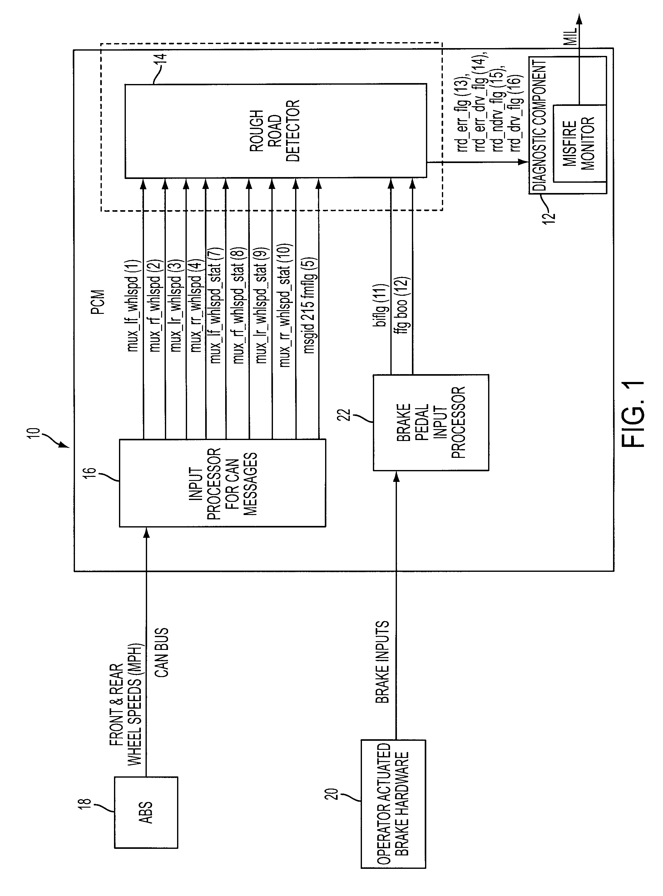
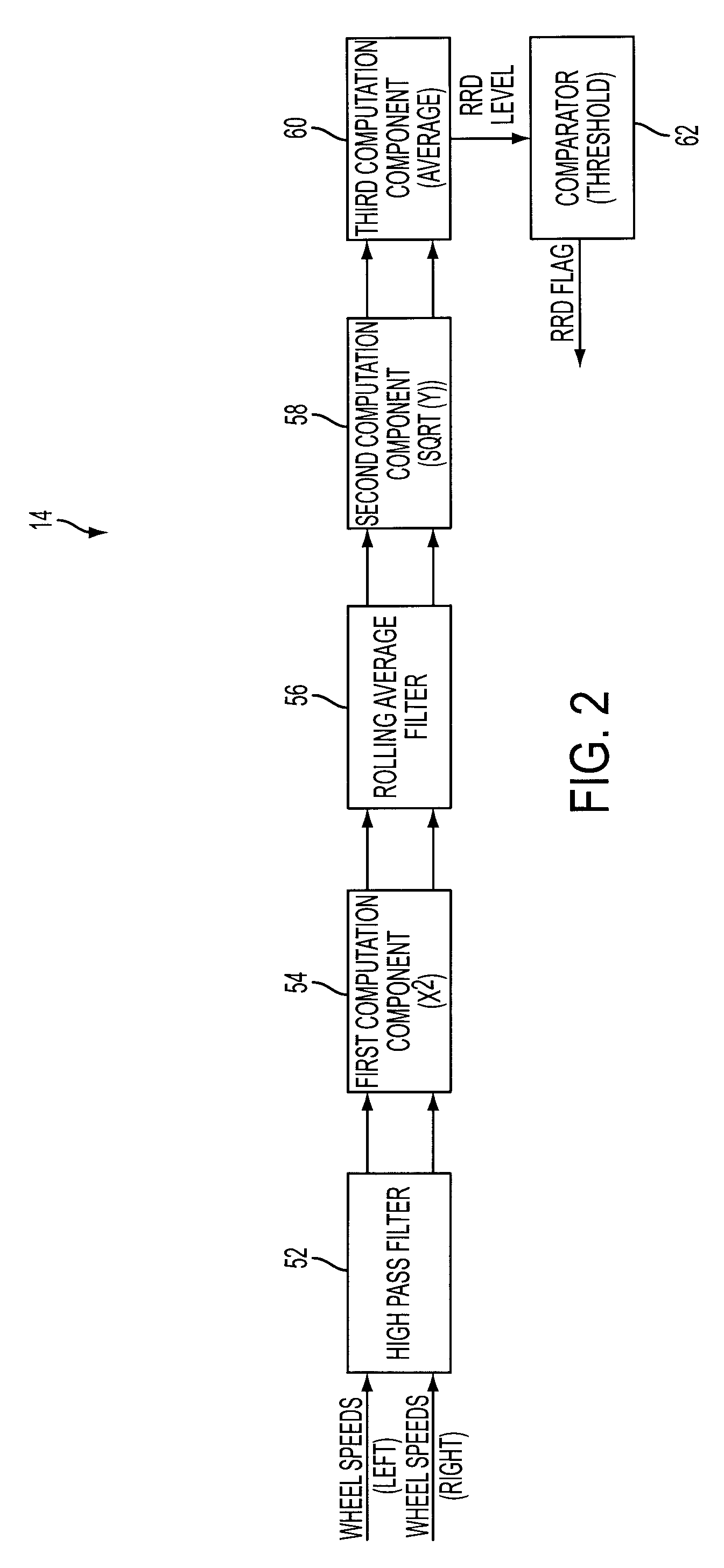
[0015]FIG. 1 is a block diagram illustrating an exemplary on-board diagnostic system 10 for a vehicle. System 10 may include a diagnostic component 12 configured to detect a vehicle operation condition and to produce an error output when the vehicle operation condition is determined to be abnormal. In the depicted embodiment, diagnostic component 12 includes a misfire monitor used in an on-board diagnostic system II (OBD II). The misfire monitor may indicate misfire by lighting a malfunction indicator lamp (MIL), and the output of the misfire monitor may be used in various engine controls. The misfire monitor may be prone to false positives (alpha error) under rough road conditions such as the large cobblestone lanes, which can cause driveline disturbances that are incorrectly interpreted as misfires by the misfire monitor. A noise disablement feature present in the misfire monitor may not be effective in reducing these errors. Incorrect misfire determinations can cause the engine t...


PUM


Abstract

An on-board diagnostic system of a vehicle comprises disabling diagnostic operation, such as a misfire monitor, based on road roughness. In one example, the disabling of the diagnostic operation is based on brake actuation and degradation of an anti-lock braking system.

Description

FIELD OF INVENTION[0001]The present application relates to a rough road detection system, specifically, a rough road detection system used in an on-board diagnostic system to reduce false positive errors from a diagnostic component.BACKGROUND[0002]Various engine components of a vehicle perform different control operations. Diagnostic components may be used in a control system to provide error outputs to indicate that an engine operation is not normal. However, the roughness of a road surface may create false positives (alpha errors) in the diagnostic components. For example, an emission oriented on-board diagnostic system (OBD II) in a vehicle may include a misfire monitor to detect misfires that may cause an overall rise in hydrocarbon emissions. The misfire monitor can be prone to false positives under extreme road surface conditions. In another example, the roughness of the road may result in an inaccurate estimation of a road surface frictional coefficient which is used to contr...

Claims


Application Information

Patent Timeline
Patent Type & Authority Patents(United States)
IPC IPC(8): G06F19/00G06F7/00B60T8/00B60W40/06B60W50/02
CPCB60W50/0205B60W50/045B60W40/06Y10T477/6745Y10T477/813Y10T477/817Y10T477/81Y10T477/87Y10T477/80Y10T477/816
Inventor ASGARI, JAHANFELDKAMP, TIMOTHYSTEPHENS, CRAIGFRIDMAN, MOSESHROVAT, DAVORVARADY, ARTHURMCCONNELL, MITCH
Owner FORD GLOBAL TECH LLC
Why Eureka
Try Eureka