Method and system for obstacle avoidance for a vehicle

a technology for vehicles and robots, applied in the field of method and system for avoiding obstacles for vehicles or robots, can solve the problems of prone to delayed reaction or indecisiveness of reactive obstacle detection systems, and the likelihood of a collision may increase markedly

Inactive Publication Date: 2011-11-15
DEERE & CO
View PDF9 Cites 21 Cited by
  • Summary
  • Abstract
  • Description
  • Claims
  • Application Information

AI Technical Summary

Problems solved by technology

However, a reactive obstacle detection system may be prone to delayed reaction or indecisiveness when computations approach boundaries, discontinuities, local maxima, or local minima.
If a vehicle is presented with an obstacle directly in its path of travel, and the obstacle detection algorithm struggles with the computations associated with boundaries, discontinuities, local maxima, or local minima, the likelihood of a collision may increase markedly.

Method used


Image

  • Method and system for obstacle avoidance for a vehicle
  • Method and system for obstacle avoidance for a vehicle
  • Method and system for obstacle avoidance for a vehicle

Examples


Embodiment Construction

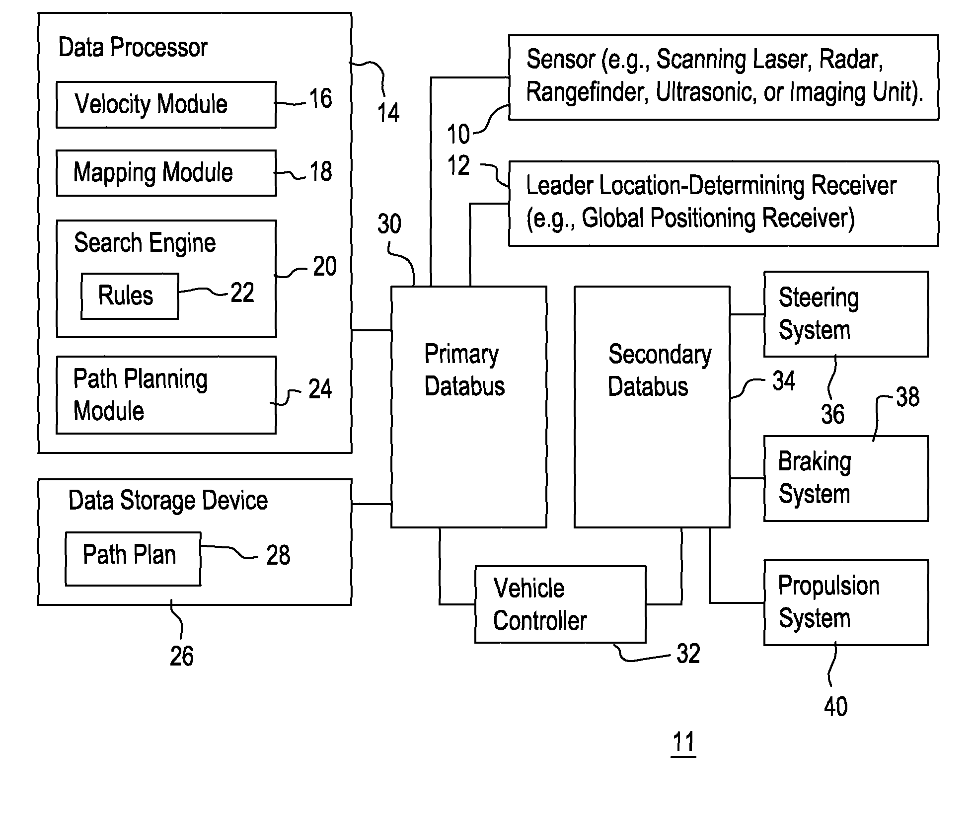
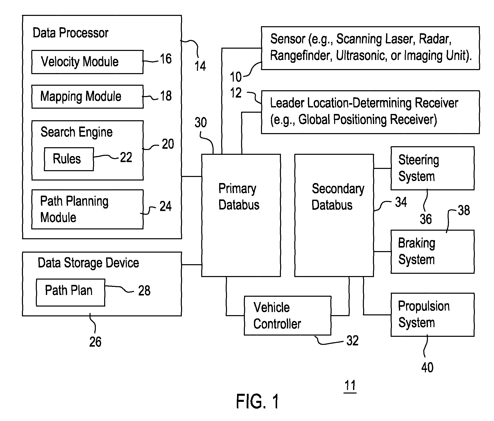
[0007]FIG. 1 illustrates one possible embodiment for the obstacle avoidance system 11. An obstacle is a stationary object, a mobile object, or another object that occupies a spatial location that is directly or indirectly between a vehicle at an origination position (e.g., origination coordinates) and a destination position (e.g., destination coordinates). The obstacle avoidance system 11 comprises a sensor 10, a location-determining receiver 12, a data processor 14 and a data storage device 26 coupled to a primary databus 30. The primary data bus 30 is coupled to a vehicle controller 32.

[0008]A secondary databus 34 is coupled to the vehicle controller 32. Although the steering system 36, a braking system 38, and a propulsion system 40 are coupled to the secondary databus 34 as shown in FIG. 1, in another embodiment the steering system 36, the braking system 38, and the propulsion system 40 may be coupled to the vehicle controller 32 via one or more transmission lines.

[0009]The data...


PUM


Abstract

A mapping module or path filtering module is arranged to identify admissible curved paths for which the vehicle is able to stop prior to reaching a detected obstacle in accordance with an observed translational velocity and an observed rotational velocity. A data processor determines a respective objective function for the candidate translational velocities and candidate rotational velocities associated with the admissible curved paths, where the objective function includes a curvature comparison term associated with the last curved path of the vehicle. A search engine or data processor selects preferential velocities, among the candidate translational velocities and candidate rotational velocities, with a superior value for its corresponding objective function. A path planning module or data processor determines the vehicular speed and trajectory for a path plan that avoids the obstacle consistent with the selected preferential velocities.

Description

FIELD OF THE INVENTION[0001]This invention relates to a method and system for obstacle avoidance for a vehicle or robot.BACKGROUND OF THE INVENTION[0002]Obstacle avoidance systems may be used to augment the performance of human operators of vehicles or for autonomous or unmanned vehicles. A reactive obstacle avoidance system may use local data of a vehicular environment to generate a control output for steering a vehicle to avoid an obstacle. However, a reactive obstacle detection system may be prone to delayed reaction or indecisiveness when computations approach boundaries, discontinuities, local maxima, or local minima. If a vehicle is presented with an obstacle directly in its path of travel, and the obstacle detection algorithm struggles with the computations associated with boundaries, discontinuities, local maxima, or local minima, the likelihood of a collision may increase markedly. Thus, there is need to expedite the search or solution for a suitable obstacle avoidance path...

Claims


Application Information

Patent Timeline
Patent Type & Authority Patents(United States)
IPC IPC(8): G06F17/10G01C21/30B60T8/32B60W30/16
CPCB60W30/09B60W30/095B60W40/072B60W40/076B60W30/16B60W2550/306B60W2554/4041
Inventor PUHALLA, JEFFREY SCOTTMAIRET, DANIEL WAYNE
Owner DEERE & CO
Why Eureka
Try Eureka