
Electronic circuit and method for resetting a magnetoresistance element

a technology of magnetoresistance element and electronic circuit, which is applied in the field of circuits, can solve the problems of inability to fully oppose the feedback circuit, and inability to eliminate the effect of hysteresis characteristic, etc., and achieve the effect of reducing the uncertainty of the sensed magnetic field due to hysteresis characteristi

Active Publication Date: 2011-11-22
ALLEGRO MICROSYSTEMS INC
View PDF90 Cites 89 Cited by
  • Summary
  • Abstract
  • Description
  • Claims
  • Application Information

AI Technical Summary

Benefits of technology

[0018]The present invention provides a sensor using a magnetoresistance element, and for which an uncertainty of the sensed magnetic field due to a hysteresis characteristic is reduced.

Problems solved by technology

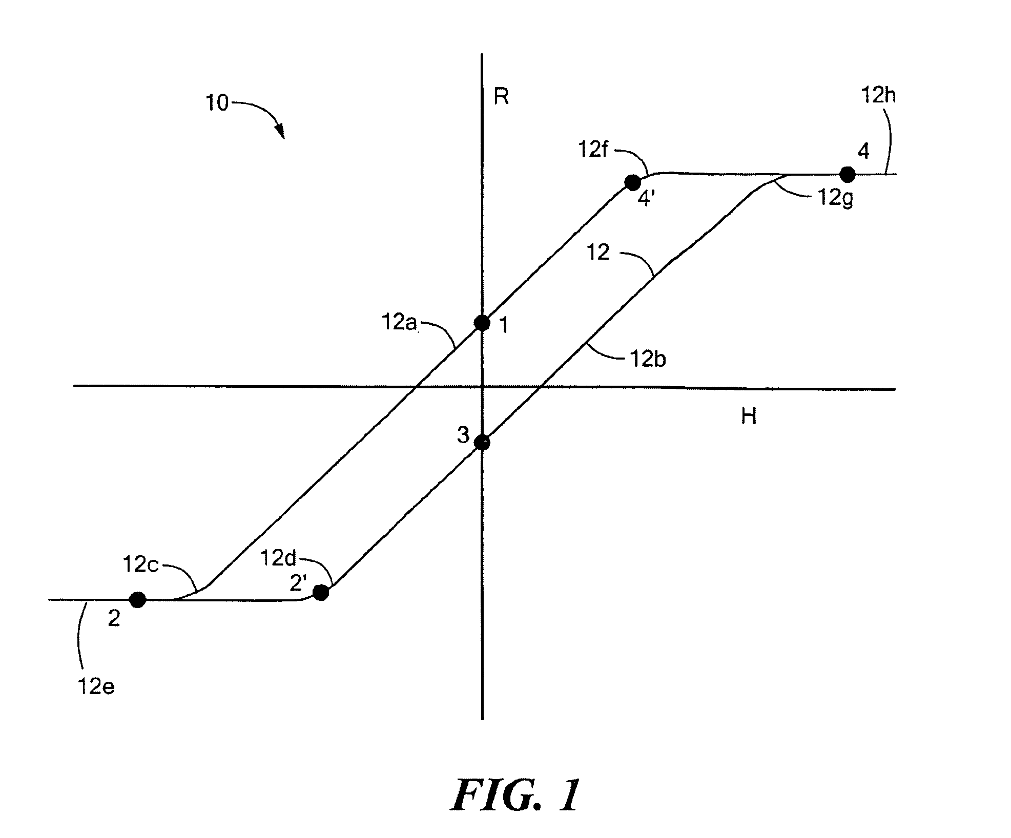
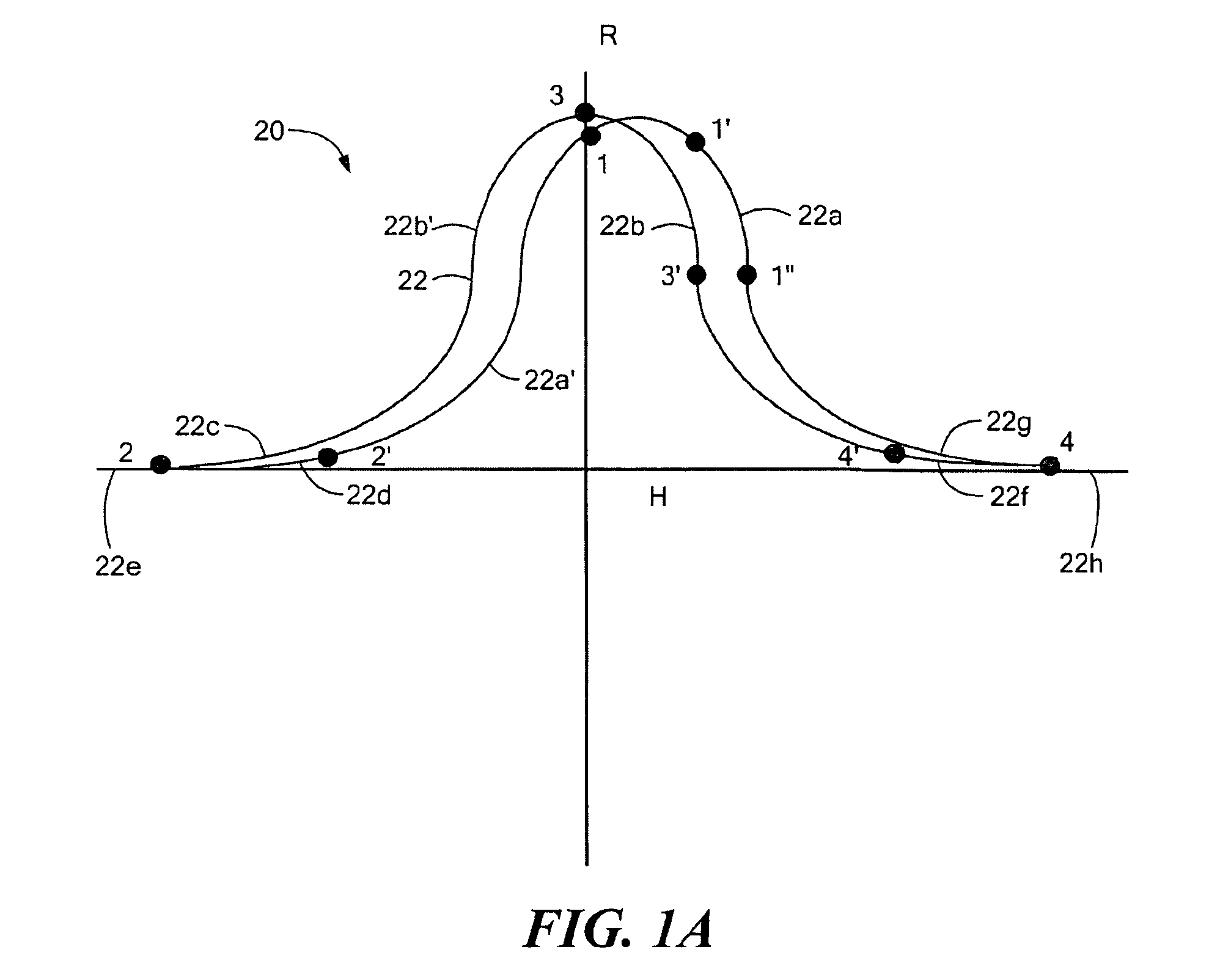
The hysteresis characteristic can result in an uncertainty as to a magnetic field being sensed by the magnetoresistance element.
Though the closed loop arrangement can eliminate the effect of the hysteresis characteristic in many situations, the closed loop arrangement is unable to eliminate the effect of the hysteresis characteristic in some situations.
For example, if the magnetic field experienced by the magnetic field sensing element is very large, and large enough that the closed loop arrangement is unable to fully oppose the magnetic field generated by current carried by the primary conductor, then the magnetic field sensing element, and in particular, the magnetoresistance element, may saturate, and the hysteresis characteristic may thereafter result in the above-described uncertainty of the sensed magnetic field.
Furthermore, the above-described closed loop arrangement includes circuit components, for example, amplifiers, which have delay times. Therefore, due to the time delay, a rapid transient in the magnetic field experienced by the magnetic field sensing element may not be fully opposed by the feedback circuit.
Thus, in this situation also, the magnetic field sensing element, and in particular, the magnetoresistance element, may saturate, and the hysteresis characteristic may thereafter result in the above-described uncertainty of the sensed magnetic field.
However, it should also be appreciated that a temporary large magnetic field experienced by a magnetoresistance element, which is generally not aligned with a maximum response axis of the magnetoresistance element, for example, which is perpendicular to the magnetoresistance element, can also cause an offset to the resistance of the magnetoresistance element thereafter, and therefore can cause the above-described uncertainty of a sensed magnetic field.
However, it is also known that many types of magnetoresistance elements have a hysteresis characteristic that can result in a greater uncertainty in a sensed magnetic field than a Hall effect element.
While current sensors using magnetoresistance elements are described as examples above, it will be appreciated that conventional external magnetic field sensors and also conventional electrical signal isolators that use magnetoresistance elements suffer from the same disadvantages due to the hysteresis characteristic.

Method used


Image

  • Electronic circuit and method for resetting a magnetoresistance element
  • Electronic circuit and method for resetting a magnetoresistance element
  • Electronic circuit and method for resetting a magnetoresistance element

Examples


Embodiment Construction

[0026]Before describing the present invention, some introductory concepts and terminology are explained. As used herein, the term “magnetic field sensing element” is used to describe a variety of electronic elements that can sense a magnetic field. While magnetic field sensing elements are shown and described below to be magnetoresistance elements, in other arrangements, the magnetic field sensing elements can be, but are not limited to, Hall effect elements or magnetotransistors. As is known, there are different types of Hall effect elements, for example, a planar Hall element, and a vertical Hall element. As is also known, there are different types of magnetoresistance elements, for example, a giant magnetoresistance (GMR) element, an anisotropic magnetoresistance element (AMR), a tunneling magnetoresistance (TMR) element, and a magnetic tunnel junction (MTJ).

[0027]As used herein, the term “magnetic field sensor ” is used to describe a circuit that includes a magnetic field sensin...


PUM


Abstract

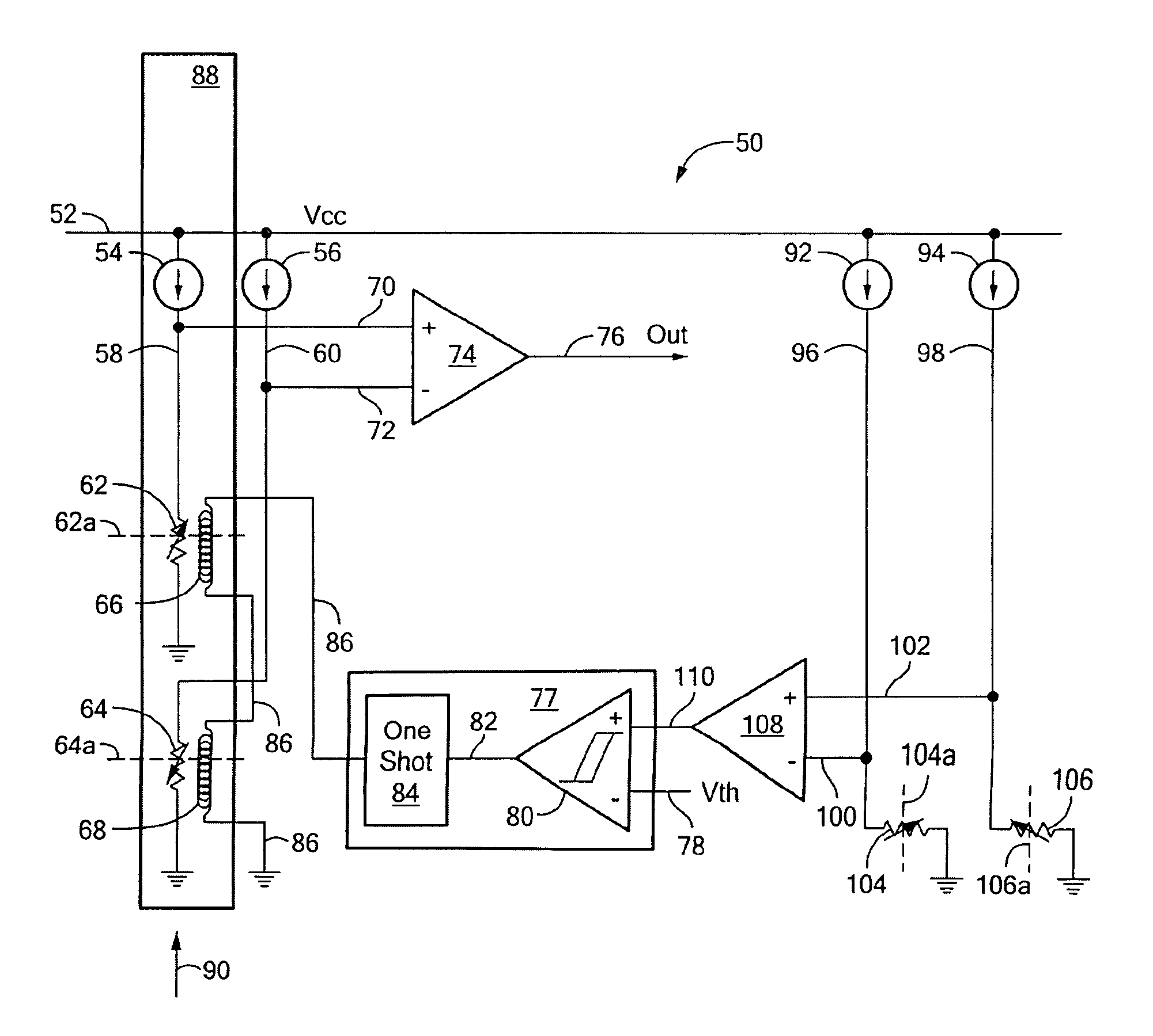
An electronic circuit includes a primary magnetoresistance element for providing a first output signal proportional to a magnetic field. The primary magnetoresistance element has a primary maximum response axis. The primary magnetoresistance element also has a hysteresis characteristic. The electronic circuit also includes a reset conductor disposed proximate to the magnetoresistance element. The electronic circuit also includes a secondary magnetic field sensing element for providing a second output signal proportional to a magnetic field. The secondary magnetic field sensing element has a secondary maximum response axis, which, in some embodiments, is substantially perpendicular to the primary maximum response axis. In operation, the primary magnetoresistance is reset in accordance with an excessive magnetic field sensed by the secondary magnetic field sensing element.

Description

CROSS REFERENCE TO RELATED APPLICATIONS[0001]Not Applicable.STATEMENT REGARDING FEDERALLY SPONSORED RESEARCH[0002]Not Applicable.FIELD OF THE INVENTION[0003]This invention relates generally to circuits that use magnetoresistance elements and, more particularly, to a circuit configured to reset a magnetoresistance element to establish operation on a known portion of a hysteresis characteristic.BACKGROUND OF THE INVENTION[0004]As is known, there are a variety of types of magnetic field sensing elements, including, but not limited to, Hall effect elements, magnetoresistance elements, and magnetotransistors. As is also known, there are different types of Hall effect elements, for example, a planar Hall element, and a vertical Hall element. As is also known, there are different types of magnetoresistance elements, for example, a giant magnetoresistance (GMR) element, an anisotropic magnetoresistance element (AMR), a tunneling magnetoresistance (TMR) element, and a magnetic tunnel junctio...

Claims


Application Information

Patent Timeline
Patent Type & Authority Patents(United States)
IPC IPC(8): G01R33/02
CPCB82Y25/00G01R33/093G01R15/205
Inventor SAUBER, JOHNTAYLOR, WILLIAM P.
Owner ALLEGRO MICROSYSTEMS INC
Learn More