Anti-pop circuit

a technology of anti-pop circuits and amplifiers, applied in the direction of push-pull amplifiers, phase splitters, gain control, etc., can solve the problems of pop, voltage to be seen at the output, and the problem of particularly pronounced problems

Active Publication Date: 2011-11-22
SYNAPTICS INC
View PDF13 Cites 10 Cited by
  • Summary
  • Abstract
  • Description
  • Claims
  • Application Information

AI Technical Summary

Benefits of technology

[0015]A circuit and method for use in a reduced pop amplifier is disclosed comprising an amplifier stage and an output stage. The output stage comprises a core output stage and a compensation network coupled to the input and output of the core output stage to provide amplifier stability. The compensation network comprises a capacitor and two switches with the first switch breaking the connectivity between the input and output of the core amplifier stage and a second switch which shunts the capacitor to ground when the control signal is low. Typically, the compensation network also comprises a resistor. Optionally, the output stage comprises a third switch which pulls the output of the core amplifier stage to ground.

Problems solved by technology

A significant issue with audio drivers in present technology arises from audio “pops.” Term “pop” in the audio field is an output disturbance caused by a sudden transition of a chip's power.
In particular, the problem is especially pronounced when power is initially turned on (or equivalently off).
Pops during when a chip powers up because the various components receive power and may cause voltage to be seen at the output even though there is no signal.
Similarly, a pop can occur when the power is switched off because energy may be stored in the circuitry and the power may inadvertently be dissipated through the output even though no input signal is received.
Furthermore, because of capacitive and inductive effects, the voltage can even spike when the power to a chip is switched on or off.
The pop issue manifests itself frequently in the driver or power portion of an audio circuit.
However, in some implementations the output stage may supply some amount of gain.
The difficulty with two-stage amplifiers is that generally they are inherently unstable.
The primary drawback to this type of solution is that it requires a sound output apparatus to be placed external to the amplifier.
As a result, the low pass filter is bulky, expensive and consumes a lot of power.

Method used


Image

  • Anti-pop circuit
  • Anti-pop circuit
  • Anti-pop circuit

Examples


Embodiment Construction

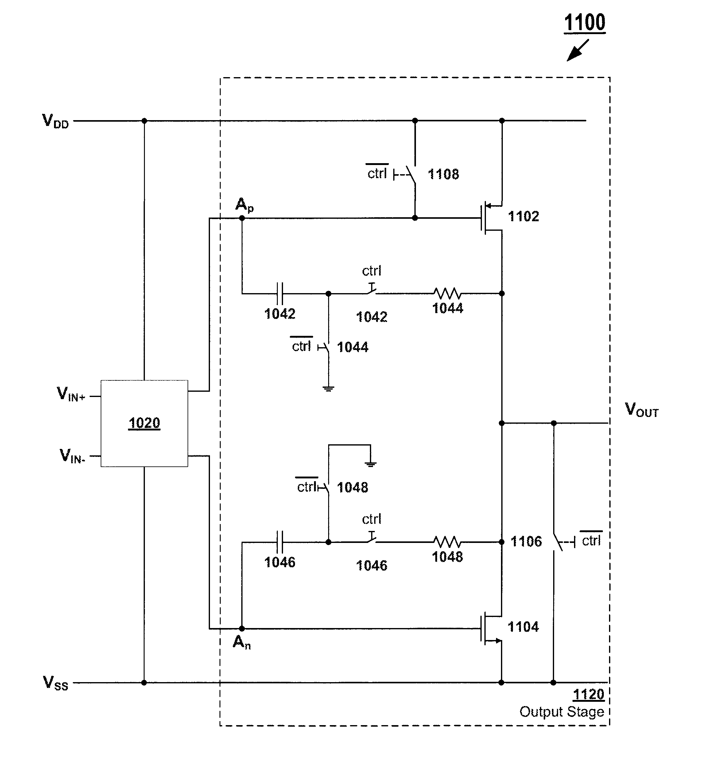
[0037]FIG. 4 illustrates an amplifier equipped with an anti-pop circuit which can be implemented with simple switches. Amplifier 400 is similar to amplifier 200. Amplifier 400 comprises amplifier stage 110 and output stage 420. Like output stage 220 of amplifier 200, output stage 420 comprises core output stage 160 and a compensation network comprising capacitor 202 and resistor 204. The described components function essentially the same as that described for amplifier 200. However, output stage 420 further comprises switch 402. When closed switch 402, it drags the output voltage VOUT to VSS which is shown as ground in FIG. 4. It should be noted that often VSS is fixed to ground. However, for the purposes of this disclosure ground and VSS are used interchangeably and should be construed to be the low power rail and not necessarily a zero voltage.

[0038]Switch 402 is controlled by a control signal. Therefore the switch initially is closed when the control signal is low but the switch ...


PUM


Abstract

Presently many audio chips suffer from pop issues, which is especially serious for single ended audio drivers. An audio pop is a disturbance in the output caused by a sudden transition of chip power, particularly when a chip is powered on or powered off. Furthermore, compensation networks included in the amplifiers on audio chips for stability offer a significant path for transmitting power disturbances to the output. Hence, circuitry is developed to suppress pops in the output stages of an amplifier.

Description

BACKGROUND OF THE INVENTION[0001]1. Field of the Invention[0002]The present invention relates generally to audio amplifiers and drivers and specifically with the mitigation of audio pops.[0003]2. Related Art[0004]A significant issue with audio drivers in present technology arises from audio “pops.” Term “pop” in the audio field is an output disturbance caused by a sudden transition of a chip's power. In particular, the problem is especially pronounced when power is initially turned on (or equivalently off). Pops during when a chip powers up because the various components receive power and may cause voltage to be seen at the output even though there is no signal. Similarly, a pop can occur when the power is switched off because energy may be stored in the circuitry and the power may inadvertently be dissipated through the output even though no input signal is received. Furthermore, because of capacitive and inductive effects, the voltage can even spike when the power to a chip is swi...

Claims


Application Information

Patent Timeline
Patent Type & Authority Patents(United States)
IPC IPC(8): H03F1/14
CPCH03F1/305H03F3/3022H03F3/45183H03F2200/144H03F2203/45526H03F2203/45534H03F2203/45674
Inventor FAN, XINLARSEN, CHRISTIANCRESPI, LORENZO
Owner SYNAPTICS INC
Why Eureka
Try Eureka