
Electric razor assembly

a technology of electric razors and parts, applied in the direction of metal working devices, etc., can solve the problems of undesirable movement of outer foils, and achieve the effect of improving contact and conformity

Inactive Publication Date: 2011-11-29
THE GILLETTE CO
View PDF22 Cites 3 Cited by
  • Summary
  • Abstract
  • Description
  • Claims
  • Application Information

AI Technical Summary

Benefits of technology

The flexible foil assembly ensures improved contact and conformity to skin contours, maintaining constant cutting performance and enhancing shaving efficiency by allowing the foils to adapt to various skin curvatures without impairing the shearing action.

Problems solved by technology

Movement of the outer foil is generally undesirable and the outer foil can conveniently be provided with a detent for engaging a foil support element to retain the outer foil against any longitudinal movement at the location of the engaged element.

Method used


Image

  • Electric razor assembly
  • Electric razor assembly
  • Electric razor assembly

Examples


Embodiment Construction

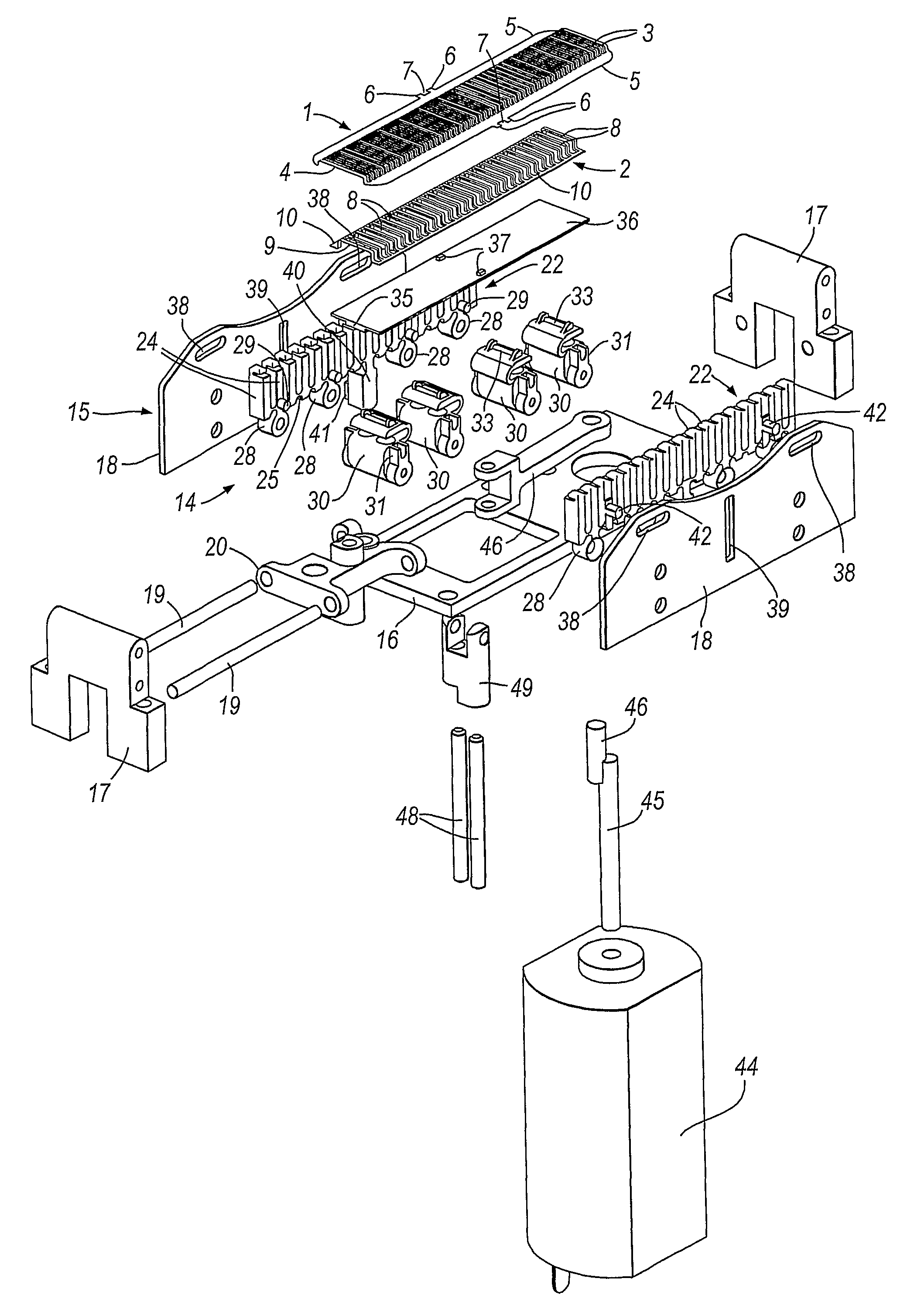
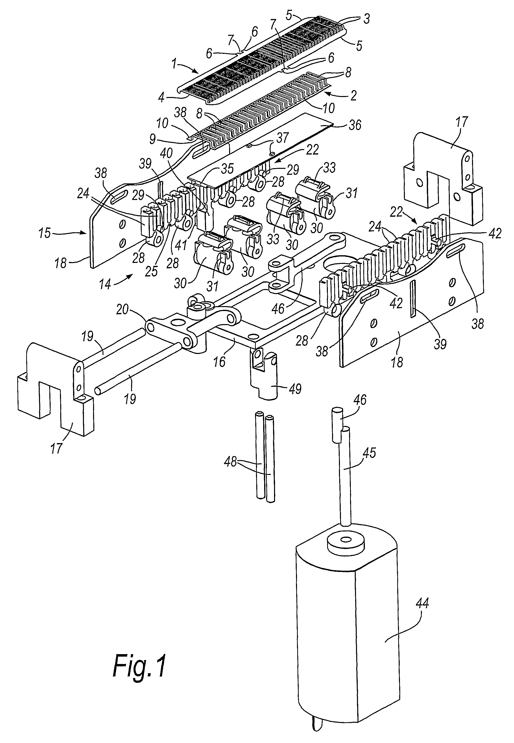
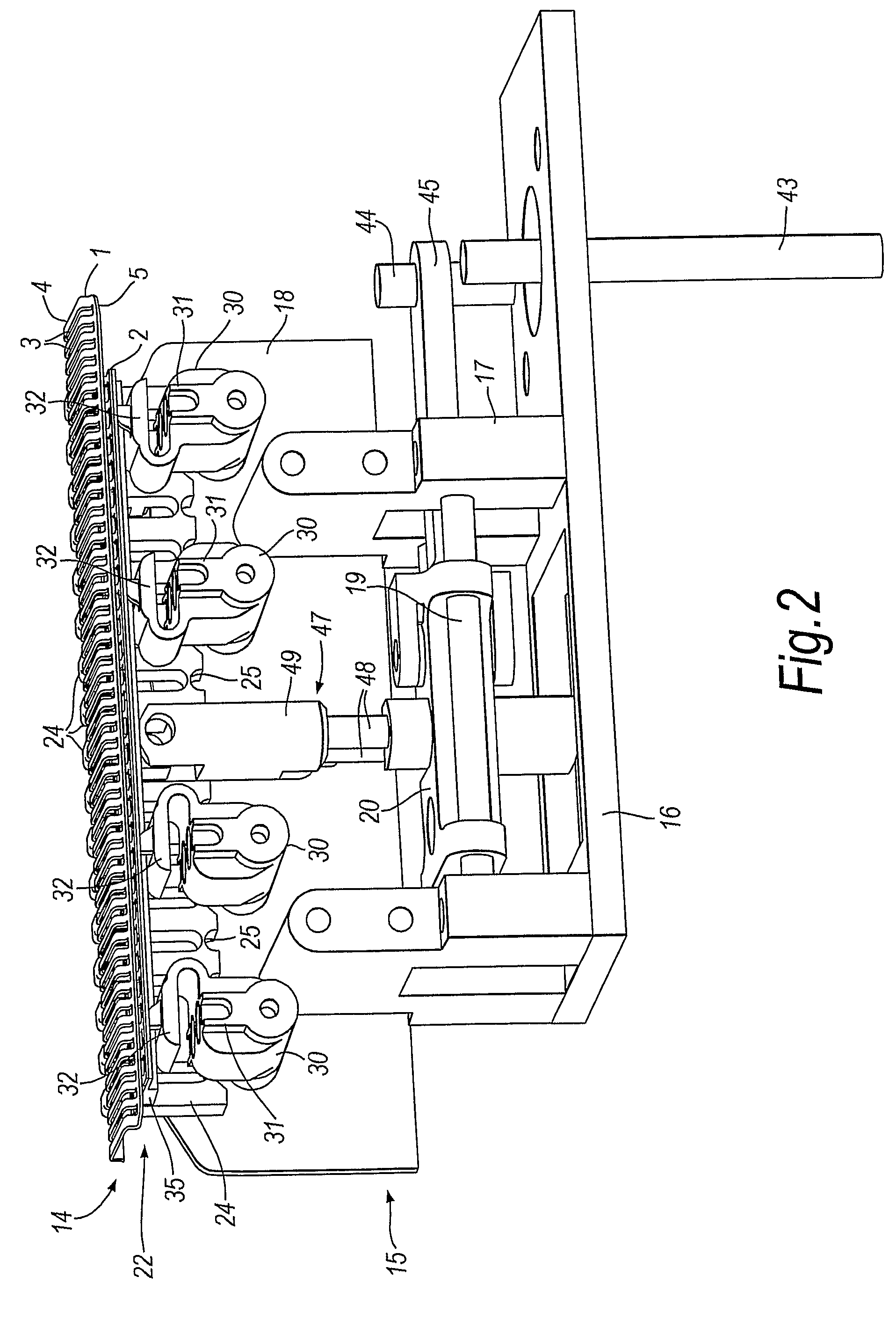
[0020]The electric razor assembly illustrated in the drawings has an outer flexible foil 1 with an upper surface for contact with the skin during shaving, and a lower surface for engagement by an undercutter consisting of an inner flexible foil 2. The outer foil has a shallow stepped profile with a main central part 4 that has openings 3 for hairs to be cut to pass through the foil, and lateral edge portions 5 which are positioned a short distance below the central part 4. The small difference in height between the central part 4 and the lateral edge portions 5 allows the foil to be supported at the edges without impeding contact between the central part 4 and the skin being shaved. Protruding from each side edge 5 of the outer foil 1 is a pair of teeth 6 defining detent notch 7 for anchoring the outer foil at a medial location along the foil as will become clear from the description that follows. The inner foil 2 is basically similar in form to the outer foil with openings 8, a rai...


PUM


Abstract

A electric razor foil assembly comprises flexible outer and inner foils (1, 2) supported by a structure (14) that is deformable to permit the foils to flex to follow concave or convex curvatures. The support structure includes two suspension members (22) supporting the foils along the respective side edges, and each support member (22) has several support elements (24) interconnected by hinges (25) and in sliding cooperation with the foils. The deformation of the suspension members is guided by guide plates located adjacent the suspension members. The foils are urged into cooperation by spring members (30) and the inner foil (2) is reciprocated by a drive arrangement including a flexible drive plate (36) disposed between the spring members (30) and the inner foil (2).

Description

CROSS-REFERENCE TO RELATED APPLICATIONS[0001]This application is a national phase of PCT / GB2006 / 00464, filed on Feb. 9, 2006, which claims priority from GB 0502936.8, filed on Feb. 11, 2005.FIELD OF THE INVENTION[0002]This invention is concerned with electric razors, and more especially with an assembly for an electric razor of the kind in which a foil is provided for contact with the skin being shaved and has openings to allow hairs to penetrate the foil in order to be severed by a shearing action between the foil and an inner member that is moved relative to the foil when the razor is in operation.BACKGROUND OF THE INVENTION[0003]There are known electric razors of the above kind in which the inner member that is driven relative to the outer, skin contacting foil, is a second foil with openings through which hairs can be inserted before being sheared between edges defined by the openings in the respective foils. A “foil” should be understood to have a thin sheet-like form, but a fo...

Claims


Application Information

Patent Timeline
Patent Type & Authority Patents(United States)
IPC IPC(8): B26B21/22B26B19/04
CPCB26B19/046B26B19/04B26B19/00
Inventor ROYLE, TERENCE GORDONBLYTH, LUKE DAVID
Owner THE GILLETTE CO
Learn More