Prepping, spraying and drying rack system for doors

a technology for spraying racks and doors, applied in the field of racks, can solve the problems of fouling the wet paint on the door, affecting the finish of the door, and affecting the quality of the door,

Active Publication Date: 2011-11-29
SCHAERER JAKE B
View PDF34 Cites 26 Cited by
  • Summary
  • Abstract
  • Description
  • Claims
  • Application Information

AI Technical Summary

Benefits of technology

[0050]Doors are deposited on the bars in a horizontal position. In the prepping phase, a door can be deposited on the top level of the rack and are supported by the horizontal section of the bars to maximize stability and minimize marring of the door's surface. In the painting phase a door can be deposited on the top level of the rack and is supported by the slanted edge of the bars to minimize contact with the wet paint coat on the door. In the drying phase a multiplicity of doors can be deposited horizontally on all levels of the rack. In this phase the doors are supported by the slanted segments of the bars to minimize contact with the wet paint.
[0058]The support structures can be made more stable by joining them with a telescoping tube or with a cable.

Problems solved by technology

Refinishing doors is time consuming labor.
Placing the door in a vertical position during this work is problematic.
Sprayed paint may reach surrounding objects and debris from the floor may foul the wet paint on the door.
Wet paint may run down a vertical door creating unsightly tracks.
It is more difficult for a painter to work on a vertical door than on a horizontal door.
A problem that emerges when multiple doors are painted is that a large surface area is needed to store the doors while they are drying.
Another problem of significance is that freshly painted doors should be allowed to dry in a location removed from the one where doors are sanded and painted to avoid unwanted dust and paint settling on them and marring their surface.
Yet another problem facing the painter is that often he must work on doors of different sizes as when he is working on several assorted cabinets.
U.S. Pat. No. 6,090,204 by Speed et al., does not allow doors of different sizes to be stacked together.
In addition, the patent makes use of brackets which may adversely shield some of the door surface from spray paint.
Furthermore these brackets cannot be used on thin doors as typically found in cabinets.
Insertion of screws on the sides might split the wood.
U.S. Pat. No. 6,561,470 by Gottfredson et al., does not allow doors to be stacked.
In addition, anchors inserted on the side of thin doors, strong enough to support the doors during prepping, might split the wood.
U.S. Pat. No. 4,491,308 by Walton et al., does not allow doors of different sizes to be stacked together.
In addition the insertion of supporting anchors on the side of thin doors, strong enough to support the doors during prepping might split the wood.
In addition, the insertion of supporting anchors on the side of the doors, strong enough for support during prepping can split the wood if the door is thin.
U.S. Pat. No. 5,509,544 by Osborne does not allow doors of different sizes to be stacked, and cannot be used on thin doors because the supporting anchors might split the wood.
These anchors are not strong enough to support doors during heavy duty work such as sanding.
This rack system is not adequate for prepping a door because it supports the door by the edges and not by the surface: the force exerted on a door during prepping may cause the door to slip and fall to the ground.
In addition, the bars traverse the vertical members of the rack 101 at an angle from the horizontal, and therefore they cannot be adjusted to support doors of different sizes by sliding them in or out.
The inability of this prior art device to support doors of different sizes is detrimental when cabinets are being refinished because cabinets are usually constructed with non-uniform door sizes even in the same house.

Method used


Image

  • Prepping, spraying and drying rack system for doors
  • Prepping, spraying and drying rack system for doors
  • Prepping, spraying and drying rack system for doors

Examples


Embodiment Construction

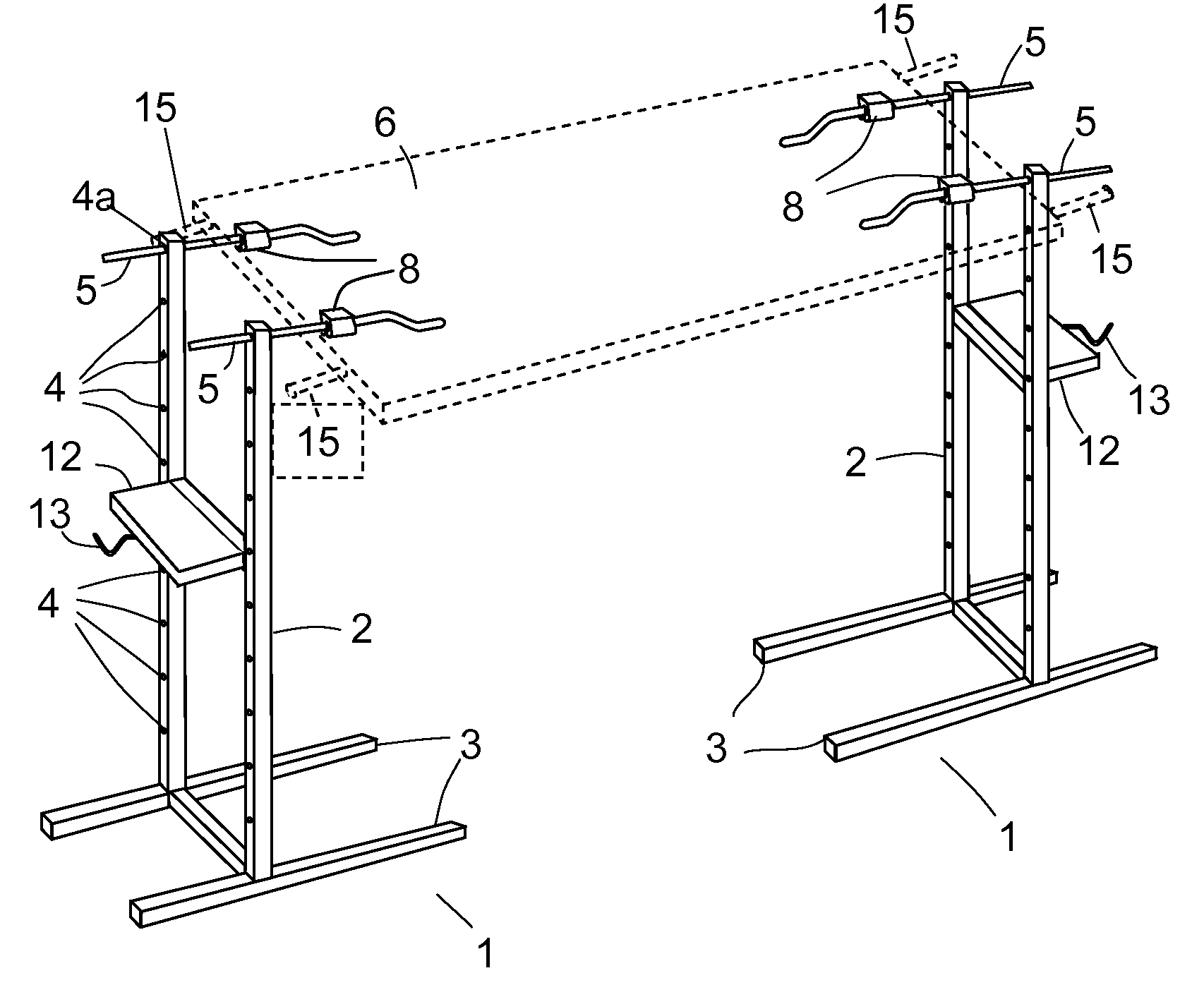
[0059]This invention can be used for the prepping, spraying and drying of flat objects such as doors, cabinet panels, cabinet doors, and window shutters. FIG. 3, FIG. 4 and FIG. 5 illustrate the invention being used for a door being prepped. Essentially it consists of a rack comprising two supporting structures 1 facing each other. Each supporting structure 1 includes a pair of vertical members 2 joined together and held erect by a base structure 3. The vertical members 2 are traversed by a series of substantially horizontal openings 4 and 4a through which bars 5 are inserted. FIG. 4 is a side view of the painter's rack system. FIG. 5 provides a close up view of the bars 5 which may have a square cross-section as shown in the figure. The bars are inserted such that one of their edges faces upward. The door or object which is to be worked on is supported by the bars. As discussed below providing bars with a square cross section is only one of many possible alternatives.

[0060]The bars...


PUM


Abstract

A painter rack for supporting one door in a horizontal position during prepping or painting, or at least one door also in a horizontal position during drying. This painter rack comprises two support structures: a left one and a right one; each support structure comprises two vertical members traversed horizontally by a number of openings; each support structure also comprises a number of bars used to support at least one door, each bar is comprised of at least two segments, the first said segment traversing slidably and horizontally an opening, and the second segment is bent with respect the first segment. Each support structure is held in place by a base structure.

Description

FIELD OF THE INVENTION[0001]This invention claims the benefit of U.S. Provisional Application No. 61 / 035,726 with the title, “Prepping, Spraying and Drying Rack for Doors” filed on Mar. 11, 2008 and which is hereby incorporated by reference. Applicant claims priority pursuant to 35 U.S.C. Par 119(e)(i). The present invention relates to racks used to support doors while they are prepped and painted and when they are stacked to dry in a horizontal position. Prepping is defined as activities performed before painting such as sanding and taping.BACKGROUND[0002]Refinishing doors is time consuming labor. Typically this work involves activities such as sanding, painting, varnishing and drying the door. Placing the door in a vertical position during this work is problematic. Sprayed paint may reach surrounding objects and debris from the floor may foul the wet paint on the door. Wet paint may run down a vertical door creating unsightly tracks. It is more difficult for a painter to work on a...

Claims


Application Information

Patent Timeline
Patent Type & Authority Patents(United States)
IPC IPC(8): B23Q3/00
CPCB05B13/0285F26B25/18
Inventor SCHAERER, JAKE B.
Owner SCHAERER JAKE B
Why Eureka
Try Eureka