Multi-group transmission of a motor vehicle

a technology of multi-group transmission and motor vehicles, applied in mechanical equipment, gearing, transportation and packaging, etc., can solve the problems of fuel consumption increase, speed decrease, speed increase,

Inactive Publication Date: 2011-11-29
ZF FRIEDRICHSHAFEN AG
View PDF18 Cites 16 Cited by
  • Summary
  • Abstract
  • Description
  • Claims
  • Application Information

AI Technical Summary

Benefits of technology

Against this background the purpose of the present invention is to indicate a multi-group transmission and a method for operating a multi-group transmission which, with means as simple, inexpensive and space-saving as possible, avoid traction force interruptions during gearshift operations and ensure a high level of shifting comfort.
Advantageously, by virtue of this intermediate gear engagement the speed loss of the vehicle during any traction shift is significantly reduced and the driving performance is thus improved and the shifting and driving comfort increased. Since the rotating masses to be synchronized can be braked by the intermediate gear the transmission brake usually provided for braking these masses during upshift processes can be omitted, so further costs, structural space and weight are saved or reduced. In addition oscillations and jerky shifts are effectively reduced, since owing to the intermediate gear the drivetrain remains pre-stressed throughout the gearshift operation, whereby an additional increase of the shifting comfort is achieved.
A particularly simple and compact structure of the arrangement is achieved by making the transmission input shaft as a hollow shaft that encloses the main transmission shaft coaxially. To reduce the structural space even more and save weight and costs, it can be provided that the clutch mechanism comprises a common outer clutch input component which accommodates the frictional clutch and the shifting clutches and which is connected on the motor side to the driveshaft, this clutch input component acting as the drive component for the frictional clutch and optionally for the shifting clutch associated with the transmission input shaft, and further, the frictional clutch acting as the drive component of the shifting clutch associated with the main transmission shaft and optionally for the shifting clutch associated with the transmission input shaft.
For a starting process the frictional clutch is operated as the starting element. For this the frictional clutch is connected, via the associated shifting clutch in a first shift position of the shifting clutch, to the transmission input shift and thus to the constant engaged for starting and the main transmission gear engaged. After starting, the shifting clutch is switched over to a second shift position in which the frictional clutch is bridged across, so that the drive power bypasses the frictional clutch and is transmitted from the clutch input component directly to the transmission input. The frictional clutch is then no longer involved in the force flow between the drive motor and the driven gear, and can be disengaged without interrupting the traction force of the vehicle.
During a gearshift the frictional clutch is now available for engaging an intermediate gear and for adapting the speed of the drive motor for a selected target gear. For this, the frictional clutch is connected directly to the main transmission shaft and thus to the transmission output via the second shifting clutch in a shift position of the shifting clutch. Thus, the torque flow for traction force support is transmitted by a direct connection of the drive input to the main transmission shaft. This renders the main transmission free from load and therefore able to be shifted, i.e. the gear engaged at the time can be disengaged and the main transmission shifted to its neutral position while the intermediate gear engaged as a direct gear maintains the positive drive of the vehicle.

Problems solved by technology

Since the vehicle is rolling during the traction force interruption undesired speed increases or speed decreases can occur.
In addition the fuel consumption can increase.
Whereas with passenger motor vehicles the traction force interruption, which affects the driving dynamics, is as a rule perceived only as annoying, for example during upshifts in a driving style of sporty orientation, in the case of medium-weight or heavy utility vehicles the driving speed can be reduced to the point where an upshift is made impossible and, on uphill stretches, undesired downshifts, creep-driving or even additional starting operations may be necessary.
However, it is limited to five gears.

Method used


Image

  • Multi-group transmission of a motor vehicle
  • Multi-group transmission of a motor vehicle
  • Multi-group transmission of a motor vehicle

Examples


Embodiment Construction

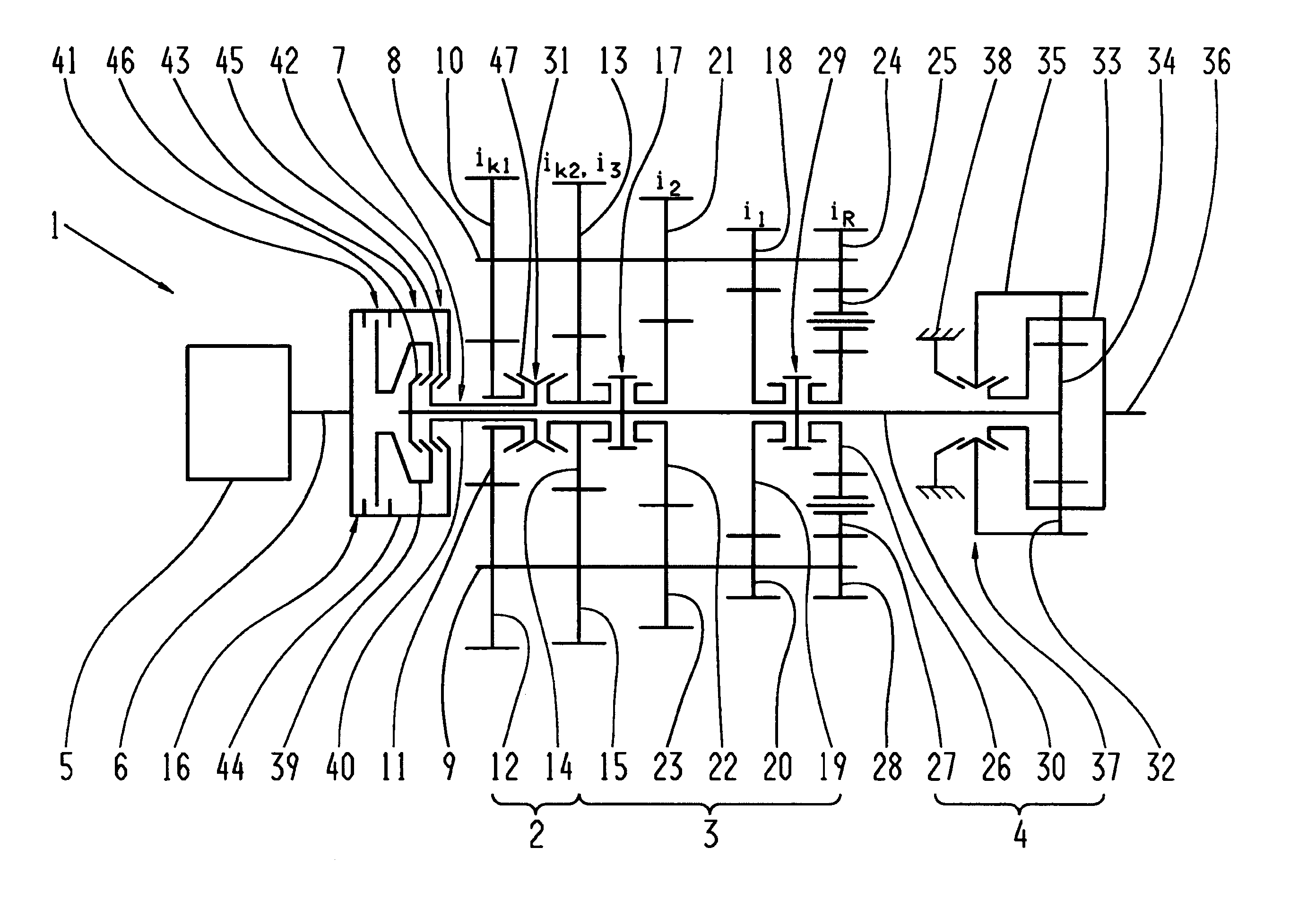
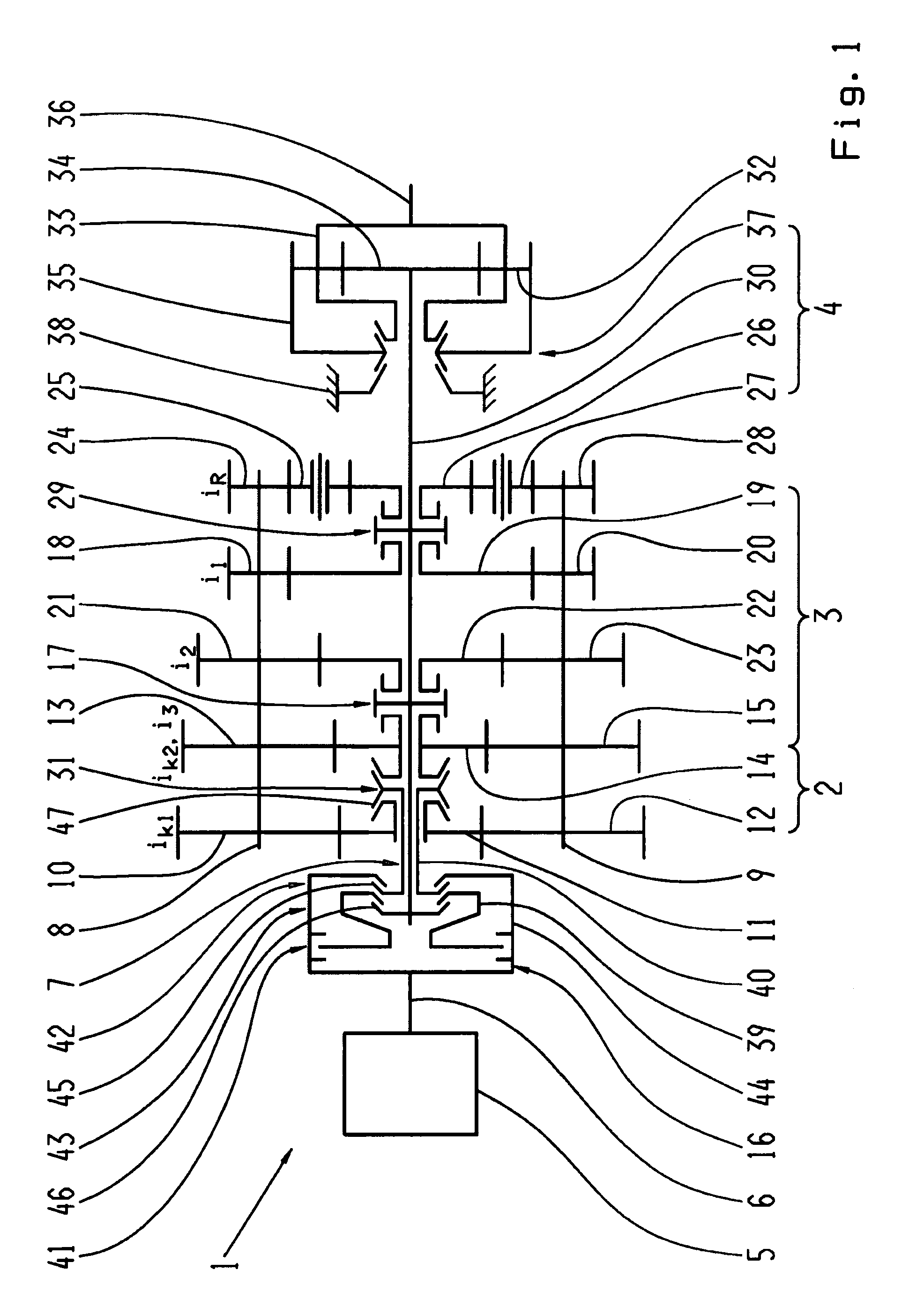
FIG. 1 shows an automated multi-group transmission which is made as a two-countershaft transmission 1 with two rotating countershafts 8, 9 mounted parallel to one another and three transmission groups 2, 3 and 4 arranged one after another, as can be provided for example in the drivetrain of a utility vehicle. Such a transmission per se, i.e. without traction force support, is known from the ZF-AS Tronic series produced by the present applicant, and with traction force support, from DE 10 2006 024 370 A1 by the present applicant, mentioned at the start.

The first transmission group 2, arranged on the motor side, is made as a two-gear splitter transmission. The second, central transmission group 3 is formed by a three-gear main or basic transmission. As the third transmission group 4 on the drive output side is arranged a downstream, two-gear range group.

The splitter group 2 has two constants ik1, ik2, respectively comprising fixed wheels 10, 12 and 13, 15 arranged in a rotationally fi...


PUM


Abstract

A multi-group transmission of a vehicle is arranged in a drivetrain and includes traction force support during gearshift operations. A clutch mechanism, including a frictional clutch and two shifting clutches is arranged between a drive motor with a driveshaft and a transmission input shaft, such that the driveshaft can be connected to the transmission input shaft by one shifting clutch in a first shift position in combination with the frictional clutch or in a second shift position with bridging of the frictional clutch, such that the driveshaft can be directly connected to a main transmission shaft by the other shifting clutch in a shift position in active combination with the frictional clutch. In a method for operating the transmission, the frictional clutch is controlled and operated in combination with the first shifting clutch as a starting clutch and with the second shifting clutch as an intermediate-gear clutch.

Description

This application claims priority from German patent application serial no. 10 2008 002 295.0 filed Jun. 9, 2008.FIELD OF THE INVENTIONThe invention concerns a multi-group transmission of a motor vehicle and a method for operating a multi-group transmission of a motor vehicle.BACKGROUND OF THE INVENTIONMulti-group transmissions consist of two or more transmission groups, usually arranged in series, by combining which a large number of gears can be produced. Increasingly, they are designed as automated gearshift transmissions consisting, for example of an input group, a main group and a downstream range group. Such transmissions are used in particular in utility vehicles since they provide an especially fine gradation of gears, for example with 12 or 16 gears, and are highly efficient. For a smaller number of gears configurations with only a main group and an input group or a main group and a range group are also possible. Furthermore, compared with manual gearshift transmissions they...

Claims


Application Information

Patent Timeline
Patent Type & Authority Patents(United States)
IPC IPC(8): F16H37/02F16H3/08F16H3/44
CPCF16H3/006F16H37/042F16H61/702F16H3/095F16H37/046Y10T74/19228F16H2200/003F16H2061/0429Y10T74/19233Y10T74/19167F16H2061/0425
Inventor DITTRICH, ALANHOFFMANN, RAYK
Owner ZF FRIEDRICHSHAFEN AG
Why Eureka
Try Eureka