Methods and systems for using intracranial electrodes

a technology of electrodes and electrodes, applied in the field of electrode assemblies and neurostimulation systems, can solve the problems of limiting the duration of use and application of this technology, and achieve the effects of stimulating large muscle groups, high stimulus levels, and high resistivity

Inactive Publication Date: 2011-11-29
AAKEN LAB
View PDF33 Cites 3 Cited by
  • Summary
  • Abstract
  • Description
  • Claims
  • Application Information

AI Technical Summary

Benefits of technology

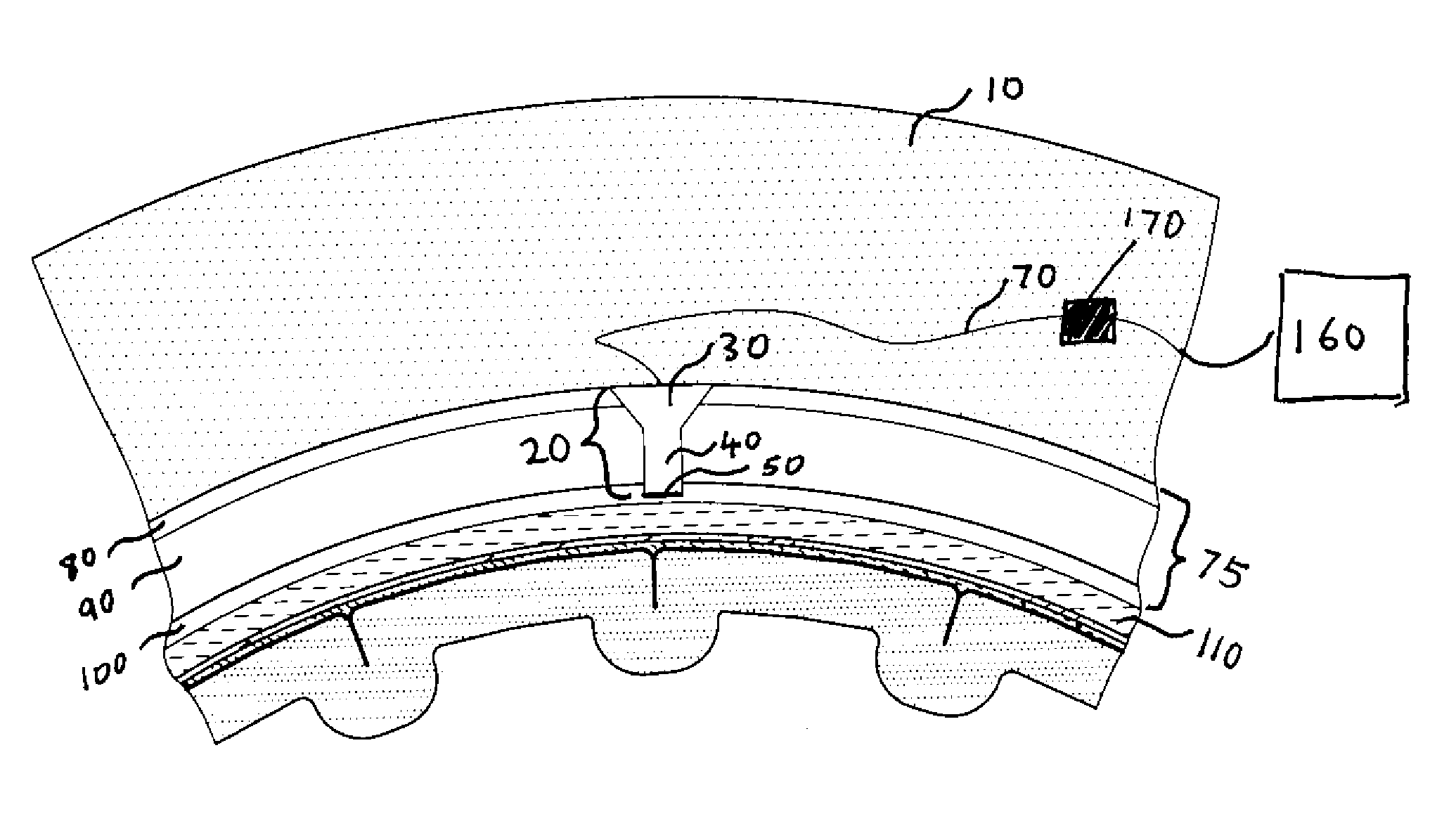
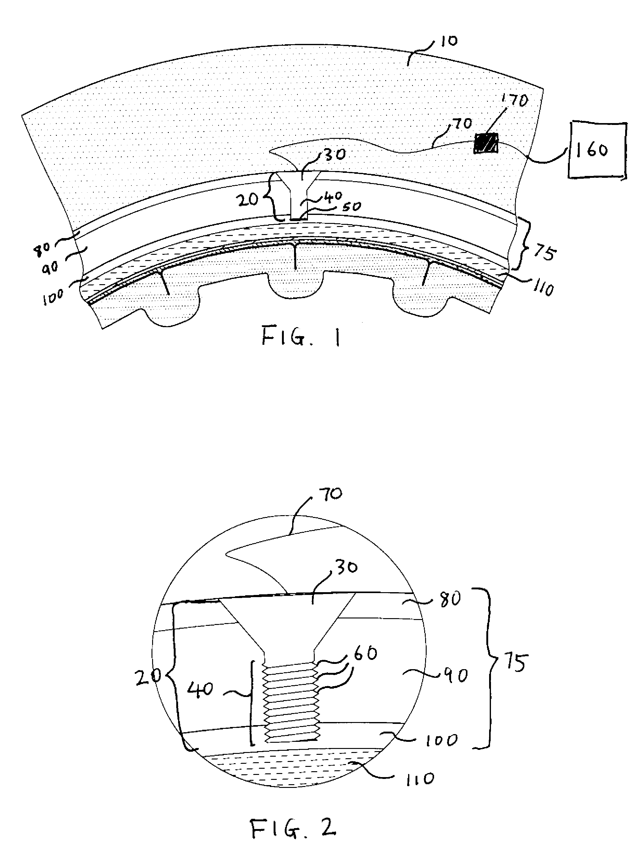
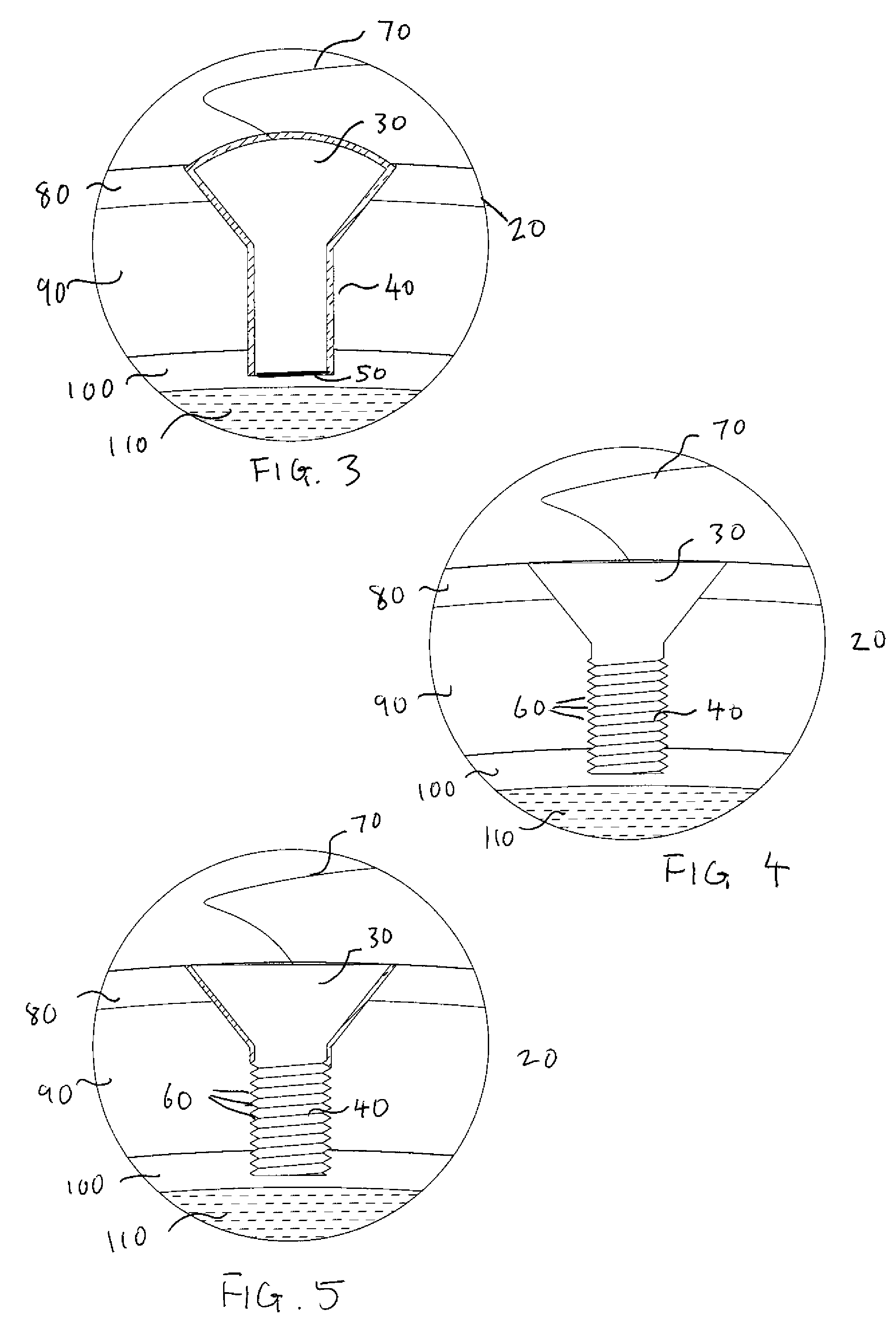
[0009]The present invention relates to intracranial electrode assemblies, neurostimulation systems, and methods for implanting or using same. In exemplary embodiments, the electrode assembly includes a body having a conductive contact surface dimensioned and configured to electrically contact a patient's skull; and an electrode head associated with the shaft. The electrode head is sized for subcutaneous positioning adjacent the subject's skull, and the electrode is of a certain length and configured such that the electrode body extends at least partially through a patient's skull but does not contact the patient's dura mater. In some embodiments, the electrode has a distal end and is of sufficient length that, when implanted, the distal end rests within the inner cortical layer of the patient's skull. The electrodes provided herein avoid many of the disadvantages, e.g. increased risk of infection, invasive implantation procedures, associated with conventional electrode design as they, unlike their conventional counterparts, are not required to directly contact the brain, penetrate or even contact the dura mater to be effective in neurostimulatory applications. Those of skill in the art are aware of the tremendous difficulties in directing electrical energy through a patient's scalp or skull to an intended site in the brain. The TMS technique, while precluding a need for invasive craniotomies or implantation procedures, is reasonably directed. In addition to the shunting of electrical energy through the scalp, the electrical current must pass through the skull, which is known to possess a high resistivity. To ensure that the electrical stimulus reaches the brain, relatively high stimulus levels need to be employed to compensate for the effects of current spreading. The use of high stimulus levels, however, has the undesirable effect of stimulating large muscle groups and causing injuries, thereby limiting the duration of use and applications for this technology. Most distinctively, the present invention applies electrical stimulus directly to a site within a patient's skull. In some embodiments, the invention can be employed in conjunction with the methods described in the parent '813 application for modeling and predicting the path of current flow when electrical stimulus is first applied to a given site, e.g. in the skull, to achieve a more focused and directed neurostimulatory effect.

Problems solved by technology

The use of high stimulus levels, however, has the undesirable effect of stimulating large muscle groups and causing injuries, thereby limiting the duration of use and applications for this technology.

Method used


Image

  • Methods and systems for using intracranial electrodes
  • Methods and systems for using intracranial electrodes
  • Methods and systems for using intracranial electrodes

Examples


Embodiment Construction

[0023]Before the present invention is described, it is to be understood that this invention is not limited to particular embodiments described, as such may, of course, vary. It is also to be understood that the terminology used herein is for the purpose of describing particular embodiments only, and is not intended to be limiting, since the scope of the present invention will be limited only by the appended claims.

[0024]Where a range of values is provided, it is understood that each intervening value, to the tenth of the unit of the lower limit unless the context clearly dictates otherwise, between the upper and lower limits of that range is also specifically disclosed. Each smaller range between any stated value or intervening value in a stated range and any other stated or intervening value in that stated range is encompassed within the invention. The upper and lower limits of these smaller ranges may independently be included or excluded in the range, and each range where either,...


PUM


Abstract

The present invention relates to electrode assemblies, neurostimulation systems and methods for implanting and using same. In exemplary embodiments, the electrode includes a body having a conductive contact surface dimensioned and configured to contact a patient's skull; and an electrode head associated with the body. The electrode head is sized for subcutaneous positioning adjacent the subject's skull, and the electrode body is of a length and configured such that the electrode body extends at least partially through the patient's skull but does not contact the patient's dura mater. As these electrodes need not directly contact the brain nor penetrate the dura mater to be effective in neurostimulatory applications, they avoid many of the disadvantages, e.g. increased risk of infection and invasive implantation procedures, associated with conventional electrode design.

Description

CROSS-REFERENCES TO OTHER APPLICATIONS[0001]The present invention is a continuation-in-part of U.S. application Ser. No. 11 / 424,813, filed on Jun. 16, 2006, which application claims the benefit of U.S. application No. 60 / 691,068, filed Jun. 16, 2005, the contents of which are incorporated herein by reference in their entirety for all purposes.FIELD OF THE INVENTION[0002]The present invention relates generally to electrode assemblies, neurostimulation systems, and methods of neurostimulation using same.BACKGROUND OF THE INVENTION[0003]A wide variety of mental and physical processes are known to be controlled or influenced by neural activity in the central and peripheral nervous systems. For example, the neural functions in some areas of the brain (e.g., the sensory or motor cortices) are organized according to physical or cognitive functions. Several other areas of the brain also appear to have distinct functions in most individuals. In the majority of people, for example, the areas ...

Claims


Application Information

Patent Timeline
Patent Type & Authority Patents(United States)
IPC IPC(8): A61B5/04
CPCA61N1/0531A61N1/0539A61N1/36082
Inventor RUSSELL, MICHAEL J.
Owner AAKEN LAB
Why Eureka
Try Eureka