
Prepreg, preform, molded product, and method for manufacturing prepreg

a technology of molded products and prefabricated products, applied in the directions of transportation and packaging, other domestic articles, synthetic resin layered products, etc., can solve the problems of unsatisfactory shaping into a complicated shape, economic burden has not been eliminated, and usage restrictions, so as to reduce the proportion of reinforcing fibers, enhance the in-plane reinforcing effect, and improve mechanical properties

Active Publication Date: 2011-12-06
TORAY IND INC
View PDF21 Cites 32 Cited by
  • Summary
  • Abstract
  • Description
  • Claims
  • Application Information

AI Technical Summary

Benefits of technology

The present invention provides a prepreg and preform that can be used for thin molded products that have been difficult to achieve using laminated molded products. The prepreg has superior isotropic mechanical properties and can be used for molded products with complex shapes. The preform is made by laminating the prepreg with other materials. The technical effects of the invention are improved mechanical properties and flexibility in molded product design.

Problems solved by technology

On the other hand, since reinforcing fibers are used in their original continuous form, they are unsuitable for shaping into a complicated shape.
In other words, since a lamination step requires time and effort and the cost increases accordingly (i.e., an economic burden caused by the lamination step will increase), usage is restricted.
However, since a lamination step requires time and effort like that mentioned above, an economic burden has not been eliminated.
However, their usage is restricted because their mechanical properties, such as specific strength and specific rigidity, are poor, they are difficult to be applied to thin molded products, and isotropic mechanical properties are hardly obtained because resin flows very much at the time of molding, and their characteristics vary widely.
However, since all of them cannot be processed to be thin like a prepreg and resin flows greatly at the time of shaping, an isotropic property may be impaired, and mechanical properties may also decline.
Also in this method, there is a limit in processing it to be thin and therefore the degree of freedom of lamination of a preform is restricted.
Furthermore, since it is impossible to produce a large number of preforms, an economic burden has not been eliminated.

Method used


Image

  • Prepreg, preform, molded product, and method for manufacturing prepreg
  • Prepreg, preform, molded product, and method for manufacturing prepreg
  • Prepreg, preform, molded product, and method for manufacturing prepreg

Examples


example 1

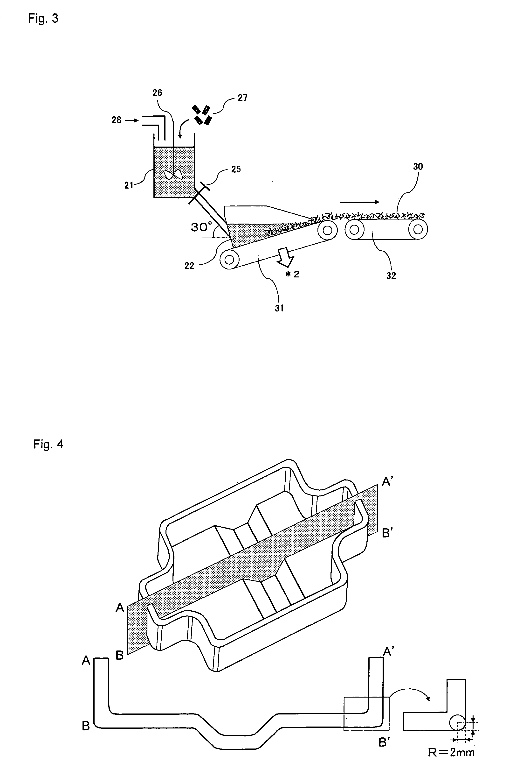
[0355]The carbon fiber 1 obtained in Material 1 was cut into 6 mm with a cartridge cutter, so that chopped carbon fiber was obtained. A dispersion liquid with a concentration of 0.1% by mass composed of water and a surfactant (polyoxyethylene lauryl ether (commercial name), produced by Nacalai Tesque, Inc.) was prepared. A carbon fiber base material was produced using the apparatus for manufacturing a reinforcing fiber base material (papermaking base material) of FIG. 3 and using this dispersion liquid and the aforementioned chopped carbon fiber. The manufacture apparatus is composed of a dispersion vessel 21, a papermaking vessel 22, and a conveyor 32. The dispersion vessel 21 is a container in a cylindrical form of 1000 mm in diameter and has a straight transport portion (the inclination angle is 30°) with an opening cock at a lower portion of the container. The transport portion connects the dispersion vessel and the papermaking vessel. A stirrer is mounted to the upper opening o...

example 2

[0358]A prepreg (2) was produced in the same manner as in Example 1 except that the Nylon 6 resin with which the carbon fiber base material was to be impregnated was adjusted so that the fiber mass content might become 52%. The properties of the prepreg are shown in Table 2. An L-shaped box-like molded product was produced in the same manner as in Example 1 except for manufacturing a preform in which seventeen prepregs (2) had been laminated. The preform was shaped well in conformity with the shape of the mold and a molded product that was high in shape quality was obtained. The properties of the molded product are shown in Table 3.

example 3

[0359]A carbon fiber base material was produced in the same manner as in Example 1 except for adjusting the basis weight of the carbon fiber base material to 70 g / m2 by adjusting the flow rate of the dispersion liquid and the speed of the mesh conveyer during papermaking. The properties of the reinforcing fiber base material are shown in Table 1. The Nylon 6 resin film with which this carbon fiber base material was to be impregnated was adjusted so that the fiber mass content might become 65% and a pressure of 5 MPa was applied at a temperature of 270° C. for three minutes, so that a prepreg (3) in which the carbon fiber base material had been impregnated with the Nylon 6 resin was produced. Since the fiber mass content was high, the impregnation with the resin became a little difficult. The properties of the prepreg are shown in Table 2. An L-shaped box-like molded product was produced in the same manner as in Example 1 except for manufacturing a preform in which seventeen prepregs...


PUM

PropertyMeasurementUnit
tensile strengthaaaaaaaaaa
thickness h0aaaaaaaaaa
lengthaaaaaaaaaa

Abstract

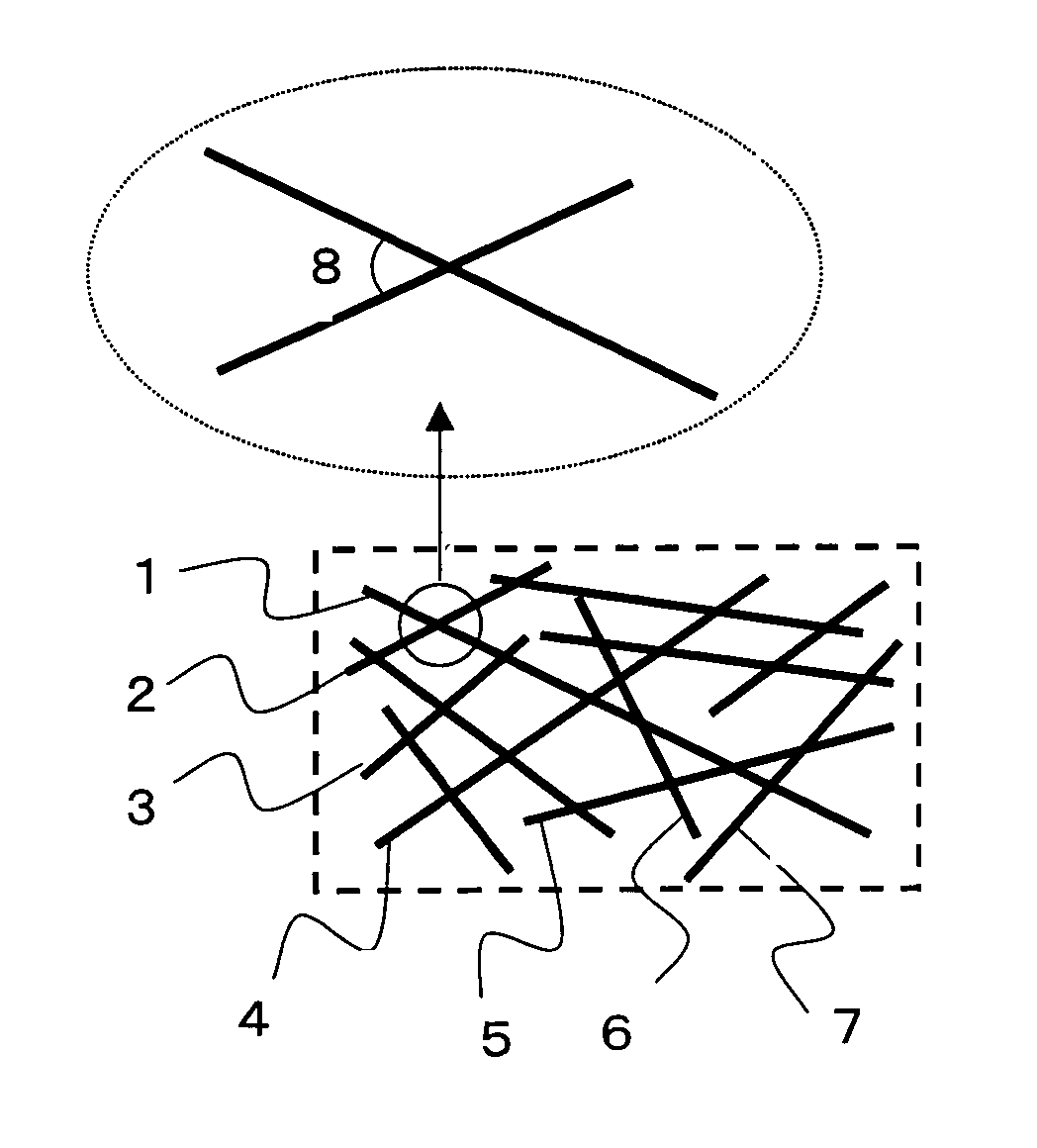
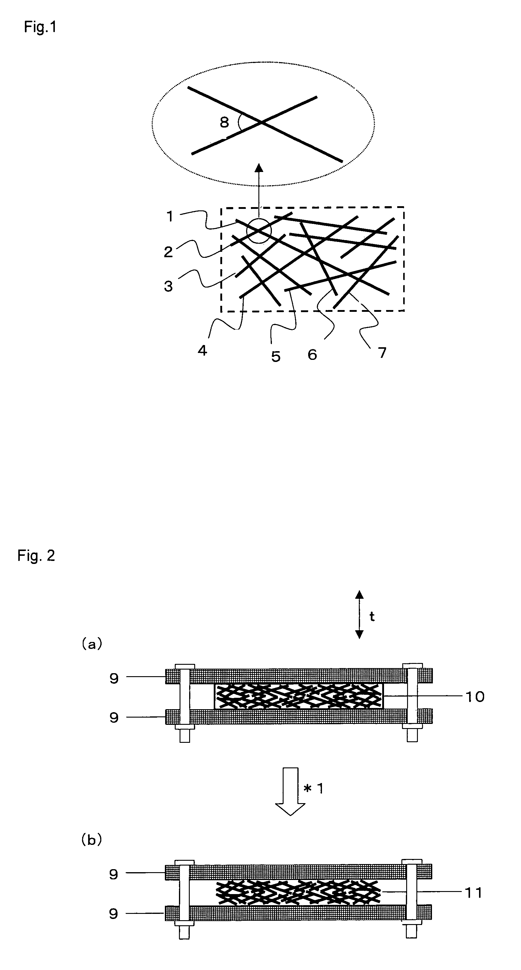
This invention is A prepreg comprising a reinforcing fiber base material impregnated with a thermoplastic resin, wherein the reinforcing fiber base material comprises from 0 to 50% by mass of reinforcing fibers each having a fiber length of more than 10 mm, from 50 to 100% by mass of reinforcing fibers each having a fiber length of from 2 to 10 mm, and from 0 to 50% by mass of reinforcing fibers each having a fiber length of less than 2 mm, the average of two-dimensional orientation angles each formed by a reinforcing filament (a) and a reinforcing filament (b) intersecting the reinforcing filament (a) is from 10 to 80°, the thickness h0 (mm) at 23° C. is 0.03 to 1 mm, and the tensile strength σ is 0.01 MPa or more.The prepreg can be applied for thin molded products which have been considered unsuitable as a laminated molded product and can provide molded products that have a complicated shape and have isotropically high mechanical properties.

Description

[0001]This application is a 371 of international application PCT / JP2009 / 063240, filed Jul. 24, 2009, which claims priority based on Japanese patent application Nos. 2008-197812, 2008-198456, 2008-198457 and 2008-198458 filed Jul. 31, 2008, and 2009-085469 filed Mar. 31, 2009, which are incorporated herein by reference.TECHNICAL FIELD[0002]The present invention relates to prepregs in which a reinforcing fiber base material has been impregnated with a resin, and a preform produced by laminating them. Particularly, it relates to prepregs in which reinforcing fibers have a specific two-dimensional orientation angle and which have a specific thickness, and to a preform produced by laminating them. Moreover, the present invention relates to a method for manufacturing a prepreg.BACKGROUND ART[0003]Fiber reinforced plastics (FRP) are light in weight and have superior mechanical properties and therefore are used widely for electrical or electric instrument applications, civil engineering or ...

Claims


Application Information

Patent Timeline
Patent Type & Authority Patents(United States)
IPC IPC(8): B32B27/04
CPCB29C70/08B29C70/50C08J3/212C08J5/24C08J5/04Y10T428/2495Y10T428/24942Y10T428/24994C08J5/247B29C2793/0036B29C70/205B29B11/16D21F1/02B32B5/24
Inventor TSUCHIYA, ATSUKIHONMA, MASATOSASAKI, HIDEAKIMURAI, SHOJI
Owner TORAY IND INC
Learn More