Termination circuit based linear high efficiency radio frequency amplifier

a technology of termination circuit and radio frequency amplifier, which is applied in the direction of amplifiers, amplifiers with semiconductor devices only, amplifiers with semiconductor devices, etc., can solve the problems of reducing battery capacity, reducing battery size, weight, or both, and increasing power consumption, so as to reduce the average current consumption of increase peak efficiency, and reduce the effect of reducing the emitter area of the amplifier stage of the rf power amplifier circuitry

Active Publication Date: 2011-12-06
QORVO US INC
View PDF7 Cites 0 Cited by
  • Summary
  • Abstract
  • Description
  • Claims
  • Application Information

AI Technical Summary

Benefits of technology

[0007]By combining the use of termination circuits to shape amplitude-based distortions and transitioning between Class AB and Class B operation, a resistive load line of the RF power amplifier circuitry may be increased, thereby increa...

Problems solved by technology

Support of such features may increase power consumption; however, market forces tend to drive down size and weight of portable wireless communications devices, thereby leading to redu...

Method used


Image

  • Termination circuit based linear high efficiency radio frequency amplifier
  • Termination circuit based linear high efficiency radio frequency amplifier
  • Termination circuit based linear high efficiency radio frequency amplifier

Examples


Embodiment Construction

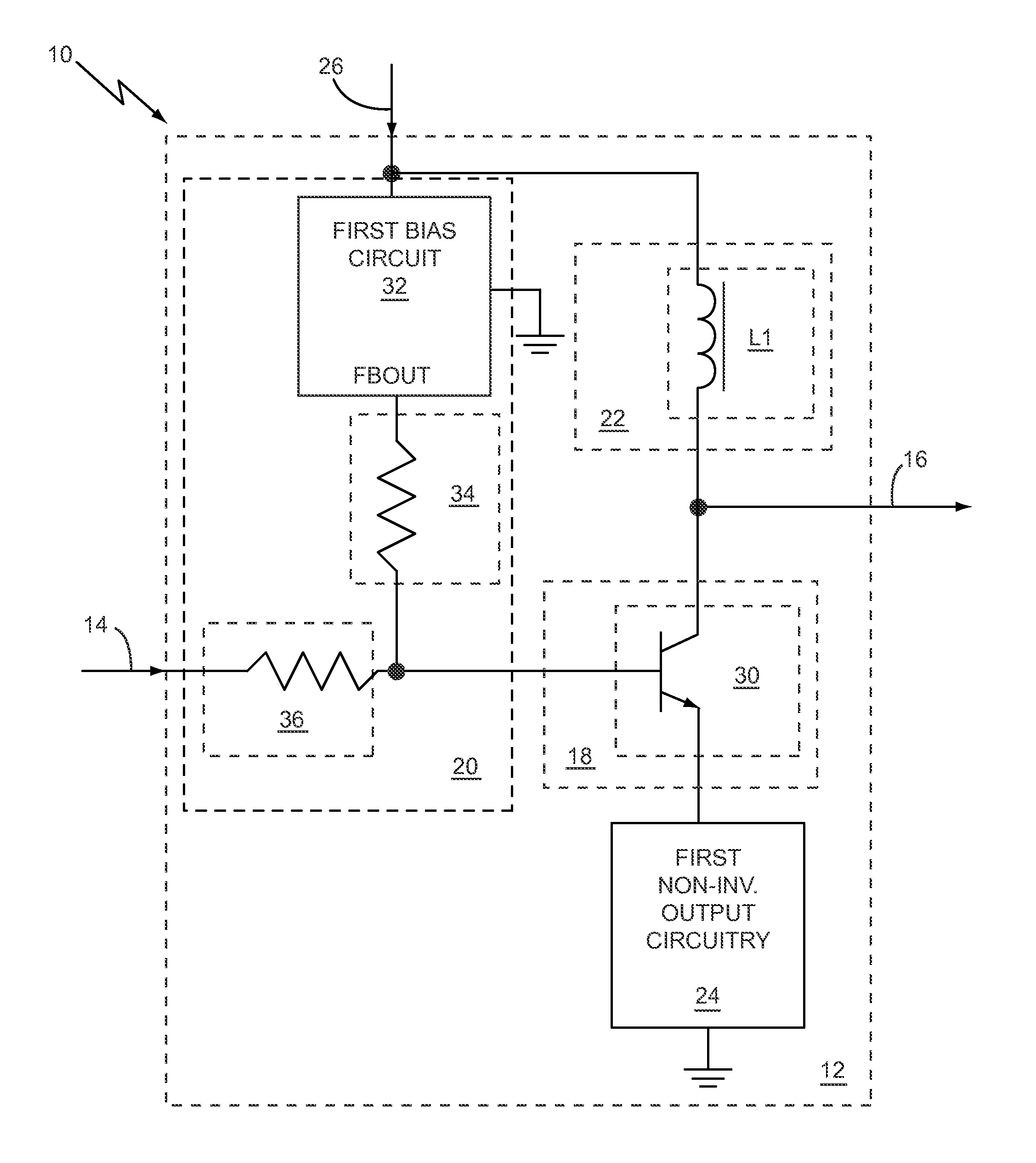
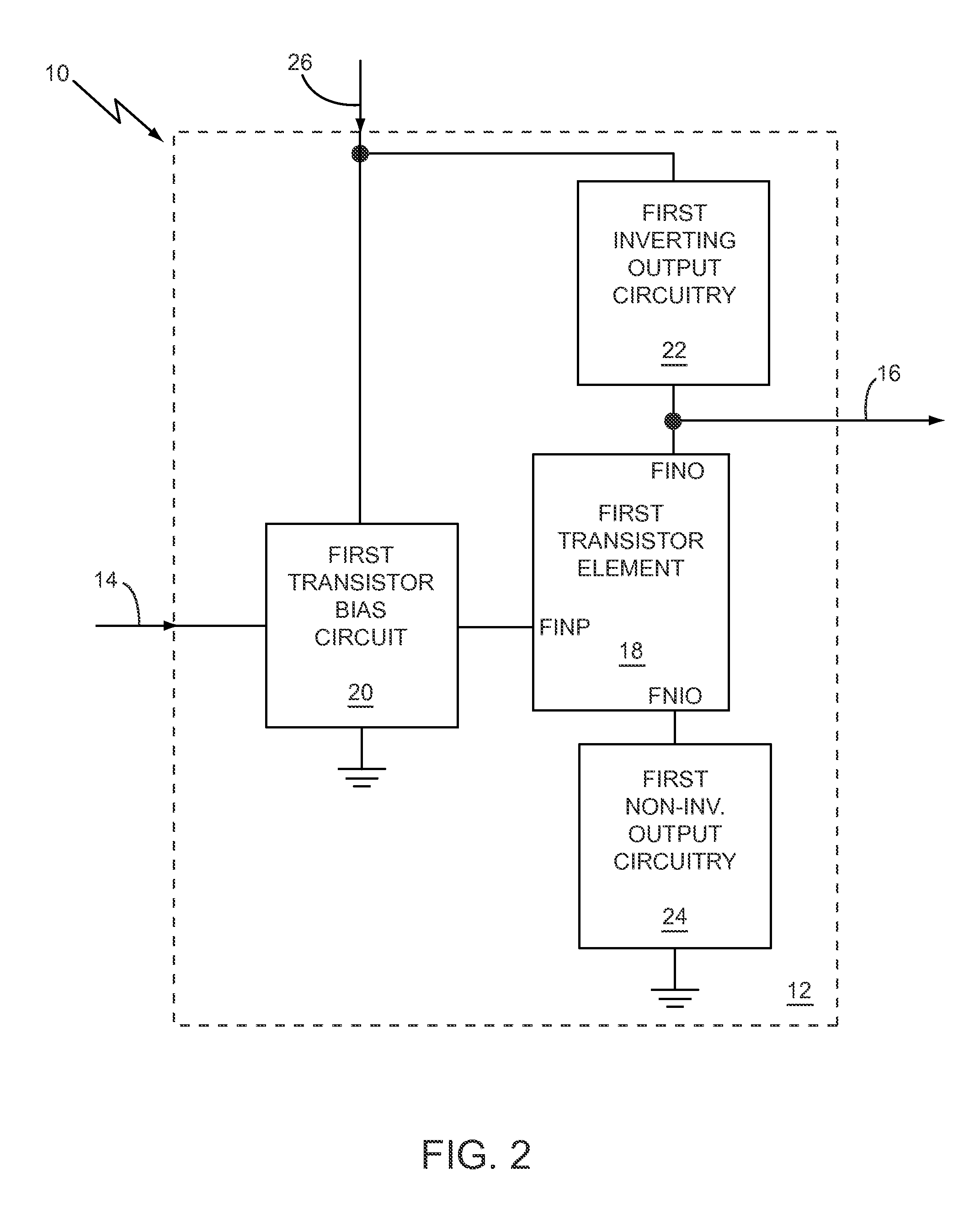
[0005]The present disclosure relates to RF power amplifier circuitry that may include a source termination circuit, a load termination circuit, or both used in an unconventional manner to shape amplitude-based amplitude modulation (AM-AM) distortion, amplitude-based phase modulation (AM-PM) distortion, or both to extend a linear operating range of the RF power amplifier circuitry. Conventional RF power amplifier circuitry may operate as a Class F RF power amplifier, which may use termination circuits to create impedance valleys at even harmonics of an RF carrier frequency to improve a saturated efficiency of the RF power amplifier circuitry. However, the termination circuits of the present disclosure may create impedance valleys that are not at even harmonics of an RF carrier frequency to shape amplitude-based distortion, thereby extending a linear operating range of the RF power amplifier circuitry. Shaping the AM-AM distortion may include reducing the AM-AM distortion, pre-distort...


PUM


Abstract

The present disclosure relates to RF power amplifier circuitry that may include a source termination circuit, a load termination circuit, or both used in an unconventional manner to shape amplitude-based amplitude modulation (AM-AM) distortion, amplitude-based phase modulation (AM-PM) distortion, or both to extend a linear operating range of the RF power amplifier circuitry. Conventional RF power amplifier circuitry may operate as a Class F RF power amplifier, which may use termination circuits to create impedance valleys at even harmonics of an RF carrier frequency to improve a saturated efficiency of the RF power amplifier circuitry. However, the termination circuits of the present disclosure may create impedance valleys that are not at even harmonics of an RF carrier frequency to shape amplitude-based distortion, thereby extending a linear operating range of the RF power amplifier circuitry.

Description

[0001]This application claims the benefit of provisional patent application Ser. No. 61 / 105,231, filed Oct. 14, 2008, the disclosure of which is hereby incorporated herein by reference in its entirety.RELATED APPLICATIONS[0002]This application is related to U.S. patent application Ser. No. 12 / 579,099 entitled BIAS-BASED LINEAR HIGH EFFICIENCY RADIO FREQUENCY AMPLIFIER filed Oct. 14, 2009, which is concurrently filed herewith and incorporated herein by reference in its entirety.FIELD OF THE DISCLOSURE[0003]Embodiments of the present disclosure relate to radio frequency (RF) amplifiers, which may be used in RF communications circuits.BACKGROUND OF THE DISCLOSURE[0004]As wireless technology progresses, communications devices are becoming increasingly integrated and sophisticated. For example, smart phones are small, portable, battery-powered wireless communications devices that may support numerous applications and wireless communications protocols. Support of such features may increas...

Claims


Application Information

Patent Timeline
IPC IPC(8): H03F3/191
CPCH03F1/0261H03F1/32H03F3/19H03F2200/108H03F2200/18
Inventor SPEARS, EDWARD T.STUTZMAN, JASON
Owner QORVO US INC
Why Eureka
Try Eureka