Flexible multitouch electroluminescent display

a multi-touch, electroluminescent display technology, applied in electroluminescent light sources, static indicating devices, instruments, etc., can solve the problems of reducing the sensitivity, response time or selectivity of the touch screen, the touch screen is often not fully transparent, and the display with integrated touch screens can be relatively expensive, etc., to achieve low incremental cost, thin and flexible display, and high density

Active Publication Date: 2011-12-06
GLOBAL OLED TECH
View PDF16 Cites 99 Cited by
  • Summary
  • Abstract
  • Description
  • Claims
  • Application Information

AI Technical Summary

Benefits of technology

[0017]The present invention provides a force activated multi-touch sensor integrated on a single flexible display substrate with an electro-luminescent display device. This combination provides an extremely thin and flexible display device which supports direct user input without image quality degradation or parallax between the imaging and touch planes. The stress or strain gauges which provide the touch sensors are integrated in or with chiplets that have a primary function of driving the display. Therefore, incorporation of these stress or strain gauges requires little incremental cost over a comparable display without these sensors. The chiplets in some arrangements will have a relatively high density and therefore, the touch screen can provide the ability to detect multiple touches with high accuracy and differentiate stress or strain induced from localized forces occurring as a result of a finger or stylus touch from stress or strain induced by bending the display. Finally, the present invention provides a compensation mechanism for correcting the signal from the stress or strain gauges in response to heat that is created by the EL devices within the display device to improve the touch signals.

Problems solved by technology

First, because the display and the touchscreen are created from separate materials and assembled together, displays with integrated touch screens can be relatively expensive.
To decrease this cost, the touch screen is often formed using low cost electronics, which decreases the sensitivity, response time, or selectivity of the touch screen.
The use of active addressing techniques, using, for example, arrays of thin film transistors (TFTs) and capacitors to permit a signal to be accumulated and read out upon demand is more desirable as it can provide better user responsiveness and sensitivity but can be very expensive.
Another issue is that the touch screen is often not fully transparent, often including reflective metal traces or other non-transparent elements to permit electrical signals to be captured and conveyed to a processor external to the touch screen.
Because this touch screen is often placed over top of the display and is not transparent, it typically reduces the contrast and therefore, the perceived quality of images presented on the underlying display.
Further, the touch screen is often not in optical contact with the display and therefore, light emitted by the display can be reflected between the two substrates, further reducing the effective contrast of the display.
Therefore, even in this touch screen, which is called “transparent,” Cheng acknowledges that the sensors have optical properties that vary from the optical properties from other regions within the overlay and are thus not fully transparent.
Another issue is that because the touch screens do not always have the ability to discretely sample data from two-dimensional locations, it is often difficult to determine where the display is being touched when the user touches the display in more than one location.
However, because there are only four sensors and a relatively rigid surface is constrained only at the location of the sensors, it is practically impossible to distinguish a force applied by two fingers at two distinct locations from a single force applied midway between the two distinct locations using a touch panel of this type.
An additional problem with these touch screens is the parallax that is induced due to the fact that the touch sensor has a finite thickness and is arranged in front of the image plane.
This further complicates usage of the display.
Such an interaction paradigm is interesting but does not provide for the direct manipulation of objects that is provided by a touch screen.

Method used


Image

  • Flexible multitouch electroluminescent display
  • Flexible multitouch electroluminescent display
  • Flexible multitouch electroluminescent display

Examples


Embodiment Construction

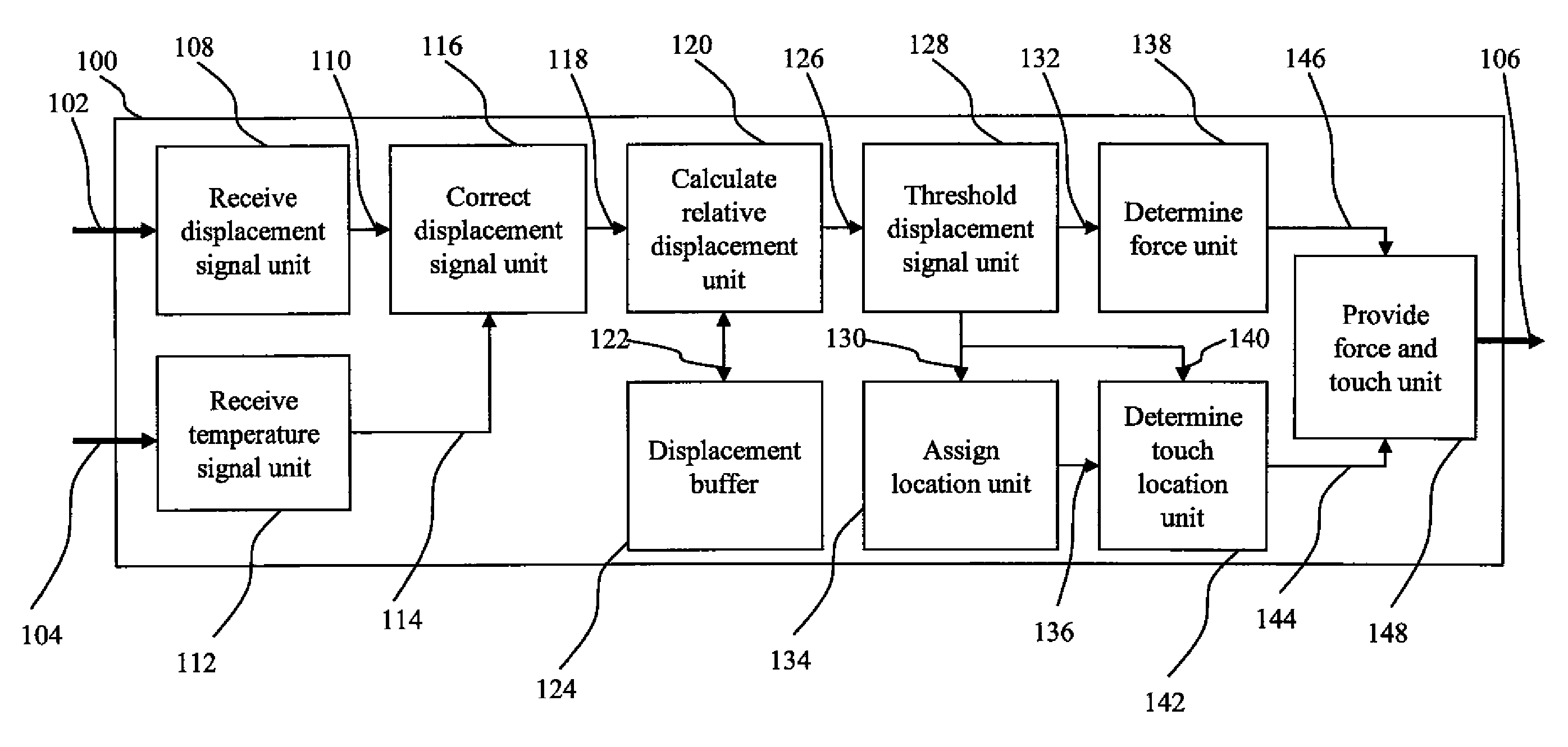
[0026]The present invention provides for an EL display on a flexible substrate with an integrated array of strain or stress sensors and a controller for displaying images on the display and receiving displacement signals to provide touch signals.

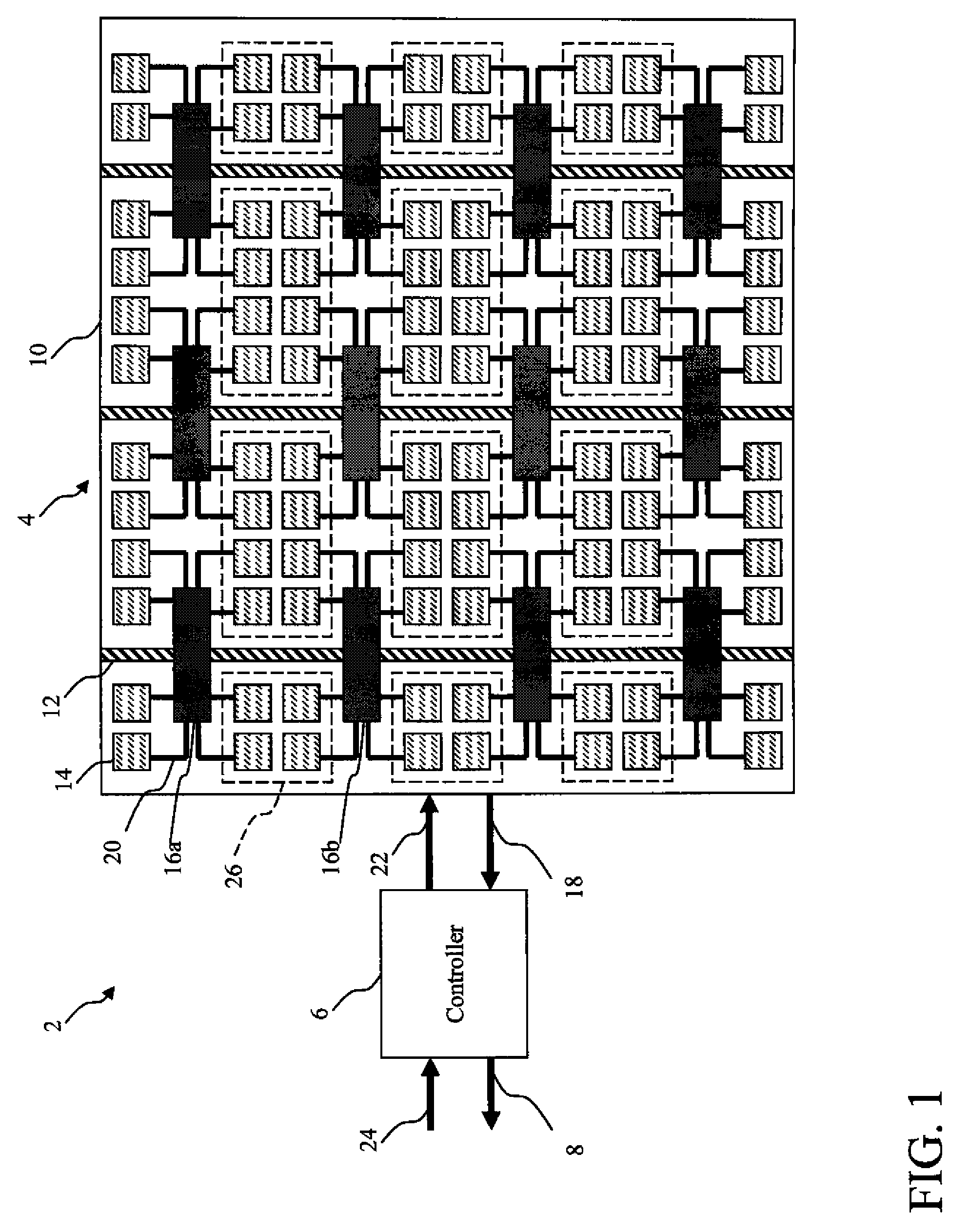
[0027]The present invention provides a display device 2 as shown in FIG. 1. This display device 2 is capable of producing touch signals 8 indicating the corresponding touch sensitive areas of the touch sensitive EL display 4 that have been touched. This flexible display device 2 includes a touch sensitive EL display 4 and a controller 6, wherein touch sensors are embedded within the EL display 4 such that touch overlays, corresponding electronics, or additional system components are not required. In some embodiments, this display is provided with a flexible support surface for constraining the deformation of the display 4.

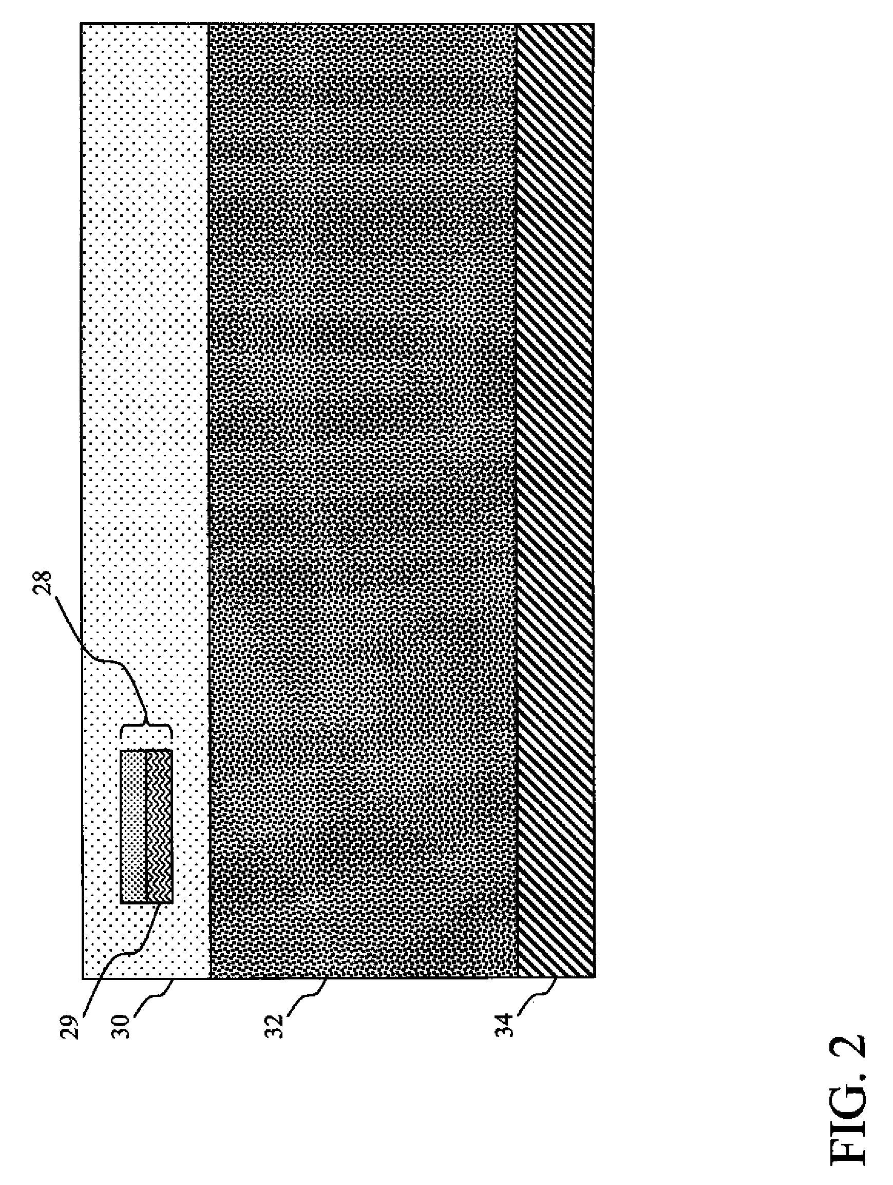
[0028]Within the present invention, the flexible display device 2 includes a touch sensitive electro-luminescent (EL) dis...


PUM


Abstract

A display device including a touch sensitive EL display having a flexible substrate; one or more power busses and one or more EL elements disposed over the flexible substrate; and a plurality of distributed chiplets arranged so that at least two chiplets are associated with each of a plurality of touch sensitive areas on the EL display and for sensing stress or strain associated with bending of the flexible substrate or the chiplet substrate to provide respective displacement signals corresponding to the touch sensitive areas; each chiplet connected to one or more of the power busses and one or more of the EL elements for modulating power from the power busses to the EL elements in response to a control signal; and a controller for providing control signals to the chiplets in response to an input image signal and for receiving displacement signals from the chiplets and producing touch signals.

Description

CROSS REFERENCE TO RELATED APPLICATIONS[0001]Reference is made to commonly-assigned, co-pending U.S. patent application Ser. No. 12 / 191,478, filed Aug. 14, 2008, entitled “OLED DEVICE WITH EMBEDDED CHIP DRIVING” to Dustin L. Winters, et al., the disclosure of which is incorporated herein.FIELD OF THE INVENTION[0002]The present invention provides a flexible EL display with an integrated, force activated multitouch touch screen that is responsive to an applied force.BACKGROUND OF THE INVENTION[0003]Traditional touch screen displays are formed by combining a display that is typically formed on a first substrate containing an array of thin film transistors with a touch screen that is formed on or in contact with a second substrate. Typically this second substrate is then positioned between the display substrate and the user.[0004]This construction creates a number of problems that should be overcome. First, because the display and the touchscreen are created from separate materials and ...

Claims


Application Information

Patent Timeline
Patent Type & Authority Patents(United States)
IPC IPC(8): G06F3/038G06F3/041
CPCG06F3/0414G06F3/0412G06F3/04146H05B33/02
Inventor MILLER, MICHAEL E.HARNER, JOHN W.
Owner GLOBAL OLED TECH
Why Eureka
Try Eureka