Adaptive distortion compensation in optical fiber communication networks

a technology of optical fiber communication network and adaptive compensation, which is applied in the direction of optical transmission, optical elements, instruments, etc., can solve the problems that other types of phase detectors and vcos cannot accomplish these functions, vcos that run at full data rates generally consume more power than those that run at fractional rates, etc., and achieve low incremental cost, easy integration into the receiver's clock, and easy correlation

Active Publication Date: 2007-05-29
LUMENTUM OPERATIONS LLC
View PDF7 Cites 18 Cited by
  • Summary
  • Abstract
  • Description
  • Claims
  • Application Information

AI Technical Summary

Benefits of technology

[0034]Therefore, the error detection circuit can measure the data eye opening in both the time and amplitude domains. By measuring one or both of these parameters, any received eye pattern can be well characterized for compensation and other purposes. Time domain error detection, when compared with spectral domain error detection, can provide a number of advantages:
[0035]First, time domain error detection provides a direct measurement of eye pattern distortion in the time domain, which is not alwa...

Problems solved by technology

In contrast, other types of phase detectors and VCOs cannot accomplish these functions.
Moreover,...

Method used


Image

  • Adaptive distortion compensation in optical fiber communication networks
  • Adaptive distortion compensation in optical fiber communication networks
  • Adaptive distortion compensation in optical fiber communication networks

Examples


Embodiment Construction

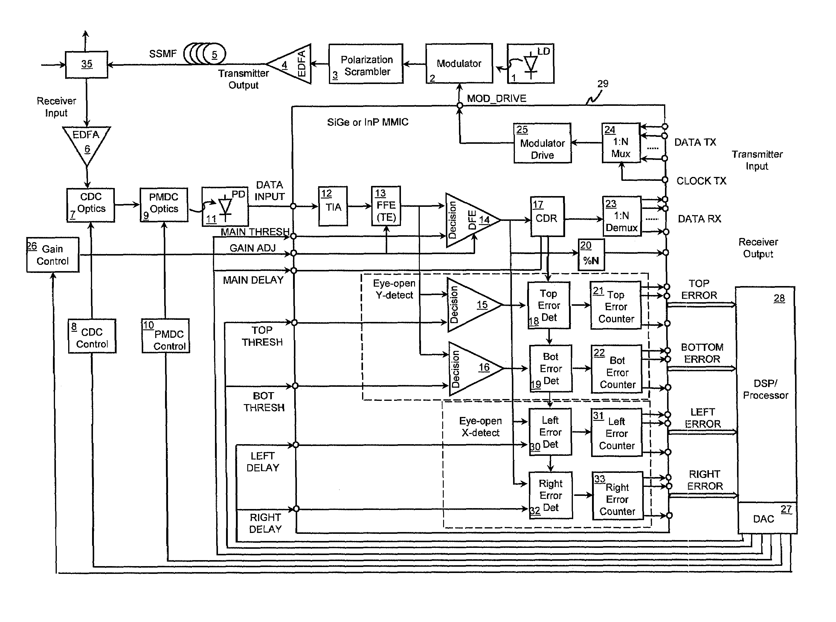
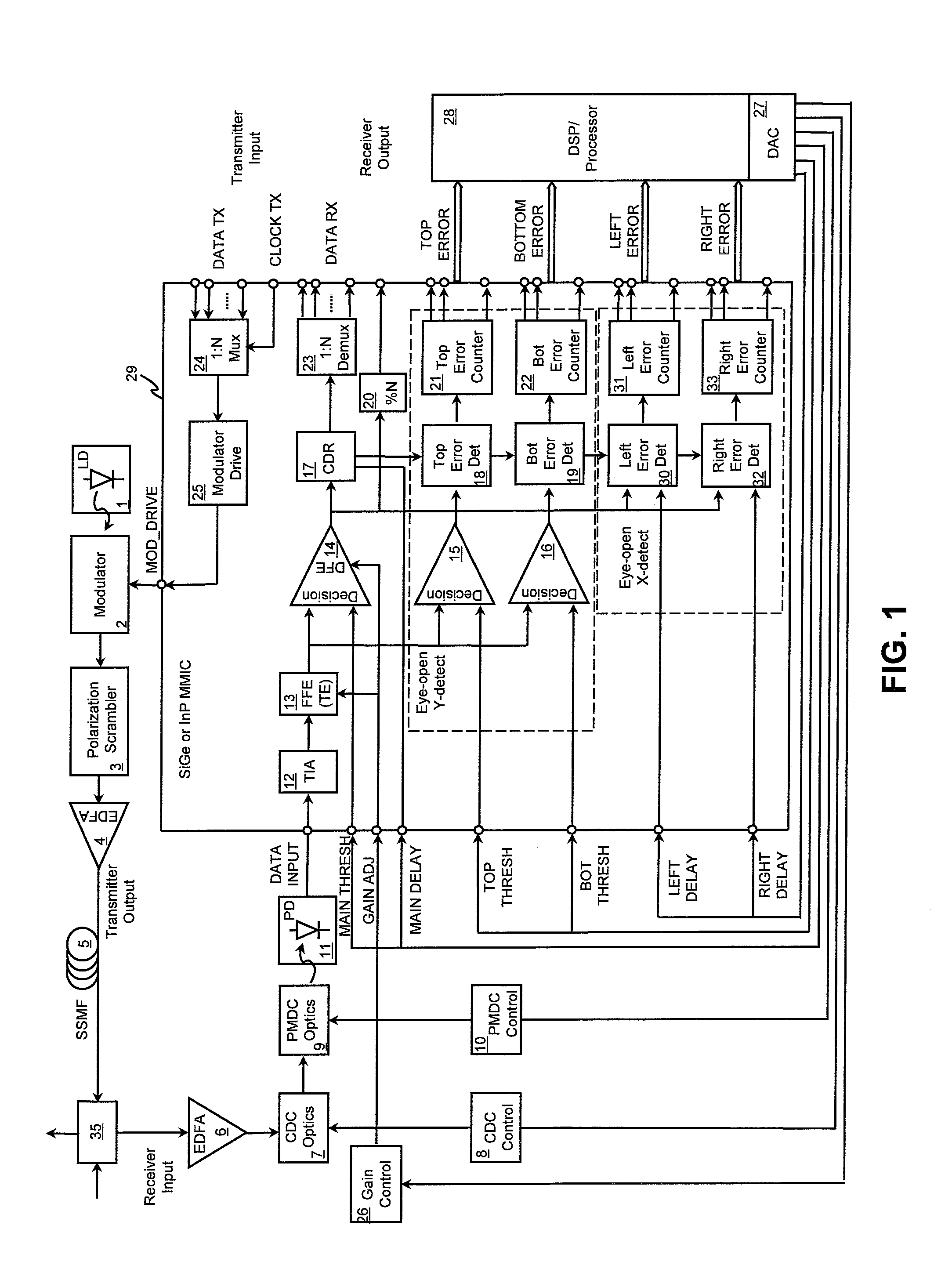
[0044]FIG. 1 shows a schematic diagram of an illustrative single chip solution for hybrid dispersion compensation and clock and data recovery in accordance with this invention. IC 29 can be fabricated using, for example, InP, SiGe or CMOS processing, depending on the desired data transmission rate.

[0045]During operation, data transmitted at lower rates can be fed in a parallel fashion into N:1 multiplexer 24, which generates a relatively high transmission rate data stream. The data stream can then be amplified by modulator driver 25 for driving optical modulator 2, which can be external to chip 29 and constructed from any appropriate optical material, such as lithium niobate. Modulator 2, in combination with light source 1, can provide a high speed optical signal.

[0046]Polarization scrambler 3 can be inserted after optical modulator 2 to randomize the polarization direction of the transmitted light. When light intensities along the principal polarization directions are the same, the...


PUM


Abstract

An apparatus for adaptively receiving, compensating, and transmitting data in optical fiber communication networks are provided. A receiver according to this invention includes at least one optical device for compensating distortion in a channel of an optical signal, at least one photodetector circuit for converting the optical signal into an electrical signal, at least one electronic device for further compensating the distortion in the electronic signal, a clock and data recovery circuit for generating a recovered data signal and a clock signal from the electronic signal, and a post-processing circuit.

Description

[0001]This application claims the benefit of U.S. Provisional Application No. 60 / 296,551 filed Jun. 7, 2001.FIELD OF THE INVENTION[0002]The present invention relates to adaptively compensating distortion in optical signals, and particularly to integrated compensation solutions for polarization mode dispersion, chromatic dispersion, and the like, in optical fiber communication networks.BACKGROUND OF THE INVENTION[0003]Polarization mode dispersion (hereinafter, “PMD”) is a signal distortion effect that can limit optical fiber transmission distances at high bit rates, such as 10 Gbits / sec (hereinafter, “Gbps”) and above. PMD is caused by variations in birefringence along the optical path that causes the orthogonal optical signal polarization modes to propagate at different velocities. The primary cause of PMD is the asymmetry of the fiber-optic strand. Fiber asymmetry may be inherent in the fiber from the manufacturing process, or it may be a result of mechanical stress on the deployed...

Claims


Application Information

Patent Timeline
IPC IPC(8): H04B10/00H04B10/18
CPCH04B10/25133H04B10/2572H04B2210/252
Inventor DAI, FAPACEK, MARK A.
Owner LUMENTUM OPERATIONS LLC
Why Eureka
Try Eureka