Display drive device

a display drive and drive technology, applied in the field of display drive devices, can solve the problems of signal collision, insufficient power consumption reduction, etc., and achieve the effects of reducing heat generation by the display drive operation, stable voltage, and optimal power consumption

Active Publication Date: 2011-12-06
BISHOP DISPLAY TECH LLC
View PDF7 Cites 0 Cited by
  • Summary
  • Abstract
  • Description
  • Claims
  • Application Information

AI Technical Summary

Benefits of technology

[0014]The display data determining circuit has a function of, when one piece of display data is switched to another piece of display data, determining a change in level of display data in the same column of a display panel from both the pieces of display data, a function of determining how electric charges accumulated between each output terminal due to a display operation are changed due to the next display operation, and a function of generating a control signal to be supplied to the output selection switch circuit based on these determination results. When it is determined in the display data determining circuit that there is a change in display data level between before and after display data is switched, display data output to each output terminal having a change and the common power supply line are temporarily switched for a predetermined period, based on the control signal of the display data determining circuit, so that the display data is caused to be temporarily at the third power supply potential. Thereby, there is not pattern dependence of display data, and in addition, the voltage of the voltage supply circuit is invariably supplied to the common power supply line, resulting in an invariably stable voltage. Therefore, power consumption of a display drive operation can be optimally reduced. Also, heat generation by a display drive operation can be reduced in an amount corresponding to the reduction of power consumption.
[0015]According to the present invention, the potential of an output terminal having a change in data output between before and after display data is switched is forcedly caused to go to the third power supply potential before driving data to be next displayed. Therefore, a change in potential of the output terminal during a drive operation can be reduced, thereby making it possible to suppress power consumption and heat generation of the display drive device. Also, there is not data dependence of display data, and in addition, the common power supply line can be invariably stably maintained at the third power supply potential.
[0016]Moreover, by performing a drive operation in a stepwise manner, a peak current during output transition of display data can be reduced, so that EMI occurring in the display drive device can also be reduced.

Problems solved by technology

Thus, there is a pattern dependence, so that power consumption cannot be sufficiently reduced.
Therefore, if the timing of the selection switch varies depending on the wiring path or the like, both the tri-state output and the common floating potential line may be selected, resulting in signal collision.

Method used


Image

  • Display drive device
  • Display drive device
  • Display drive device

Examples


Embodiment Construction

[0034]Hereinafter, embodiments of the present invention will be described with reference to the accompanying drawings.

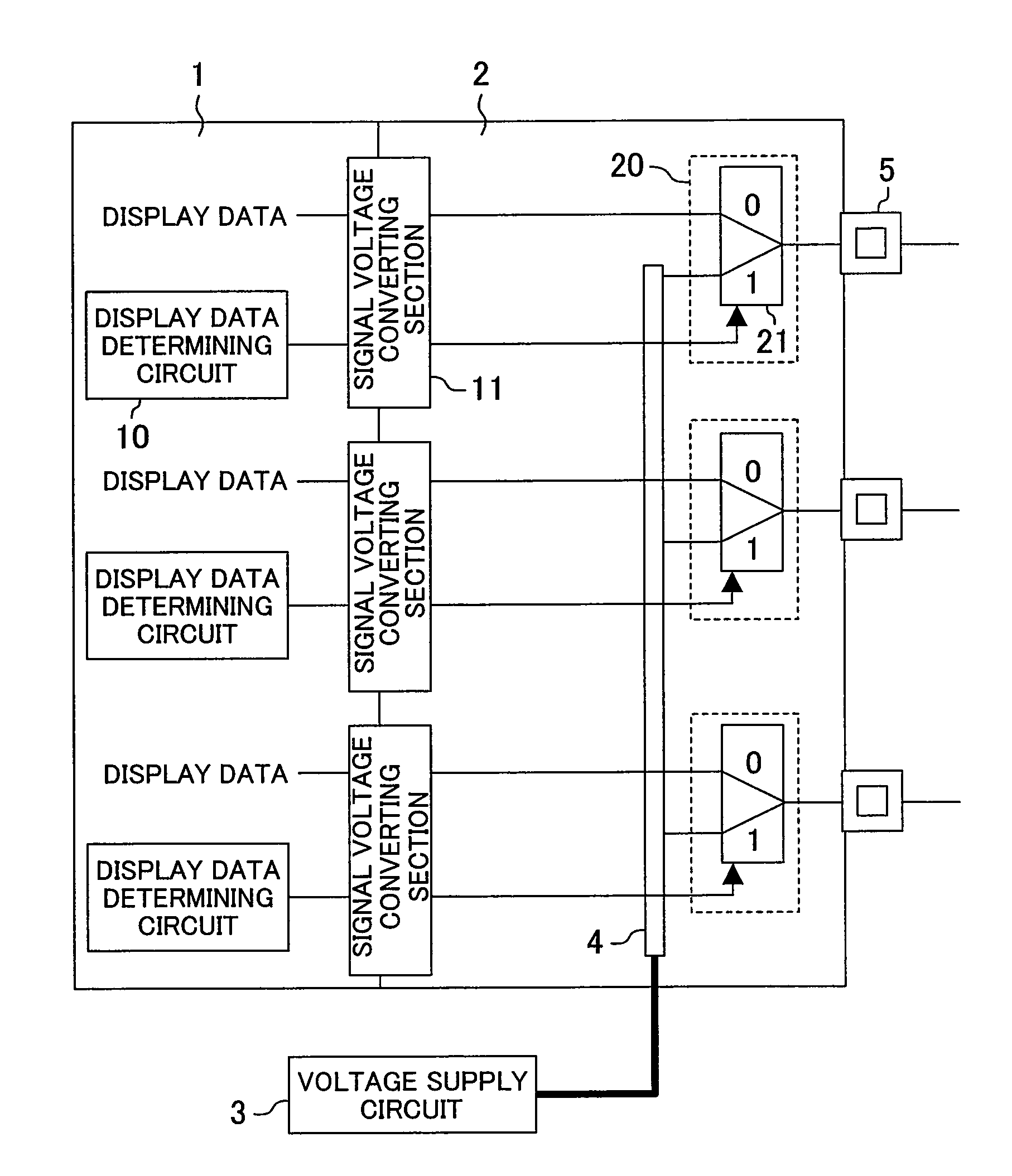
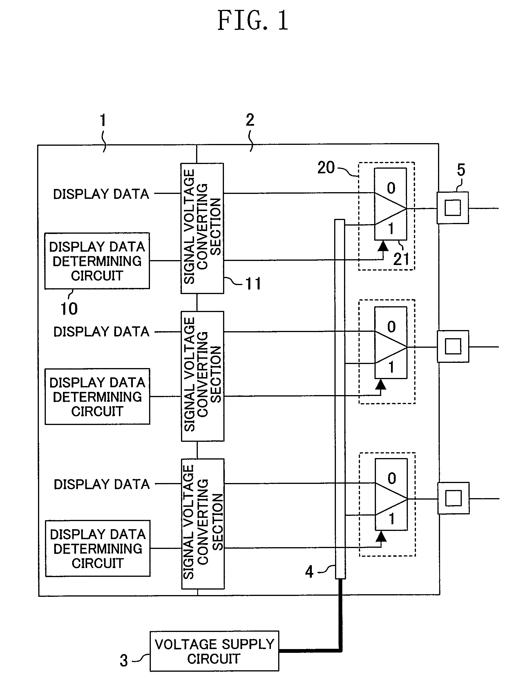
[0035]FIG. 1 shows an exemplary configuration of a display drive device according to the present invention. In FIG. 1, the display drive device comprises a low-voltage circuit section 1, a high-voltage circuit section 2, a voltage supply circuit 3, a common power supply line 4, output terminals 5, display data determining circuits 10, signal voltage converting sections 11, and output selection switch circuits 20 each including a selector 21 having two inputs and one output. For example, a first power supply potential for driving the low-voltage circuit section 1 is 3.3 to 5 V, a second power supply potential for driving the high-voltage circuit section 2 is about 80 V, a third power supply potential that the voltage supply circuit 3 supplies to the common power supply line 4 is about 40 V.

[0036]The output selection switch circuit 20 forcedly causes the potential of a...


PUM


Abstract

A display drive device includes a low-voltage circuit section driven by a first power supply potential and a high-voltage circuit section driven by a second power supply potential higher than the first power supply potential. The display drive device further includes a voltage supply circuit for supplying a third power supply potential different from the first and second power supply potentials, a common power supply line for connecting the third power supply potential to each of a plurality of output terminals, an output selection switch circuit for temporarily switching between display data output via the high-voltage circuit section to each output terminal, and the common power supply line, during a predetermined period, and a display data determining circuit for generating a control signal for controlling the output selection switch circuit. Thereby, the common power supply line is temporarily selected and controlled without signal collision when display data is switched.

Description

BACKGROUND OF THE INVENTION[0001]1. Field of the Invention[0002]The present invention relates to a display drive device for driving a display panel.[0003]2. Description of the Related Art[0004]In recent years, plasma display panels (PDPs) that have a thin thickness, a large screen, and high definition, have attracted attention. The PDP comprises a plurality of discharge cells (pixels) arranged in a matrix. An image is displayed on the PDP by utilizing light emission when discharge occurs in the discharge cells.[0005]A typical AC PDP has a plurality of display electrodes arranged in parallel and a plurality of data electrodes arranged orthogonal to these display electrodes. A display drive device drives these data electrodes, and therefore, can be considered to drive capacitive load.[0006]As the screen size, definition and luminance of PDPs have been more and more increased, display drive devices for driving the PDPs increasingly require a larger number of outputs and a higher voltag...

Claims


Application Information

Patent Timeline
Patent Type & Authority Patents(United States)
IPC IPC(8): G06F3/038G09G3/28G09G3/20G09G3/288G09G3/296G09G3/298
CPCG09G3/296G09G2330/021G09G2330/022G09G2330/045G09G2330/08
Inventor MORIYAMA, SEIICHISEIKE, MAMORU
Owner BISHOP DISPLAY TECH LLC
Why Eureka
Try Eureka