Marker selection method for hologram recording device

a hologram and selection method technology, applied in the field of marking selection methods, can solve the problems of reducing the recording capacity of data, unable to detect the position of the record image, and unable to accurately locate the marker position

Inactive Publication Date: 2011-12-06
PIONEER CORP
View PDF47 Cites 1 Cited by
  • Summary
  • Abstract
  • Description
  • Claims
  • Application Information

AI Technical Summary

Problems solved by technology

In this case, the accurate position of the marker cannot be detected, and thus the position of the record image cannot be detected.
However, there is such a technical problem that the space for division becomes a useless area, resulting in a reduction in a recording capacity for recording the data.

Method used


Image

  • Marker selection method for hologram recording device
  • Marker selection method for hologram recording device
  • Marker selection method for hologram recording device

Examples


Embodiment Construction

[0081]Hereinafter, the best mode for carrying out the present invention will be explained in each embodiment in order with reference to the drawings.

[0082](Hologram Recording / Reproducing Apparatus)

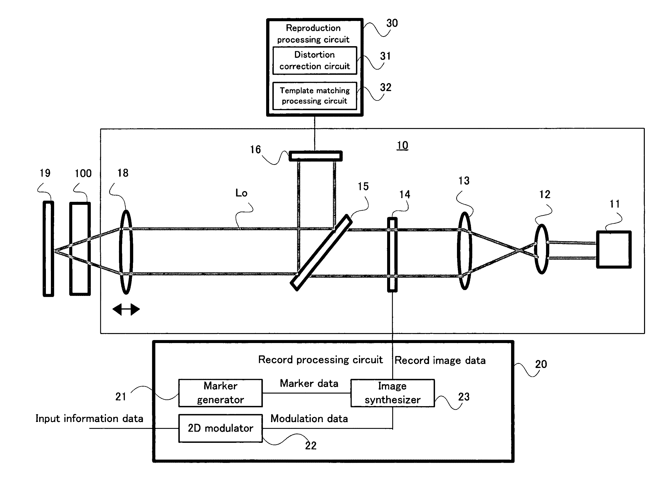
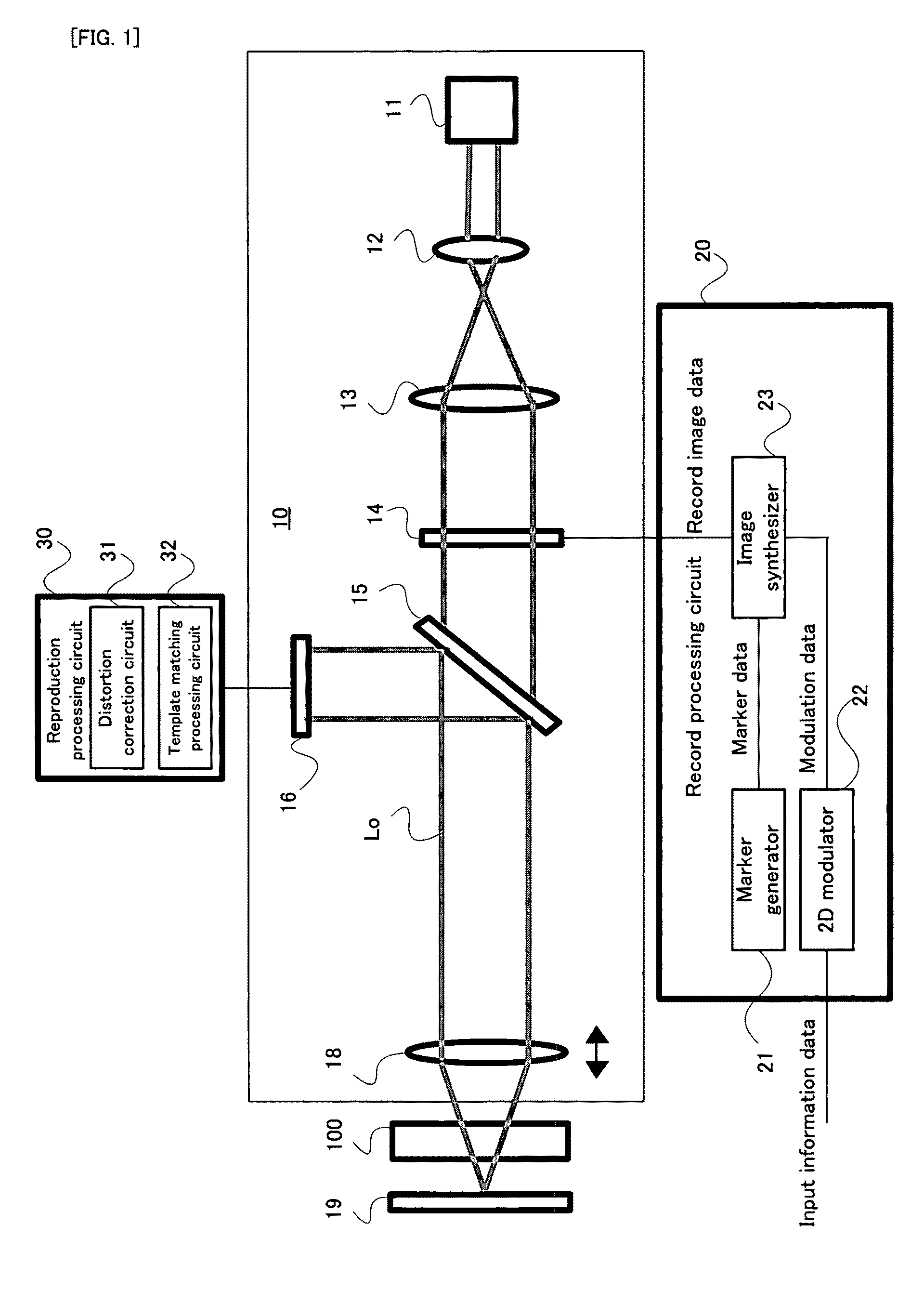
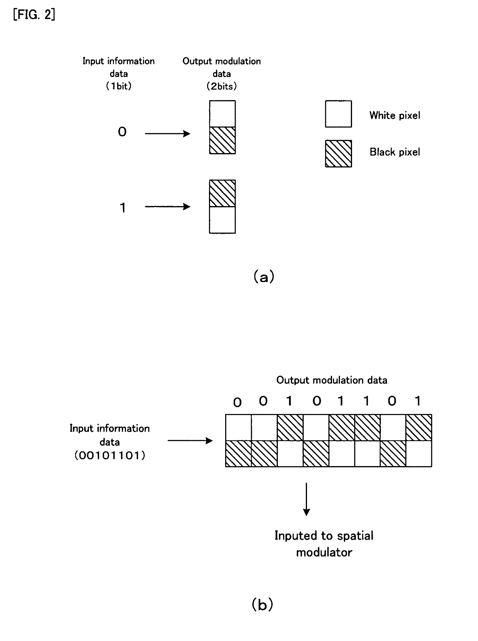
[0083]Firstly, with reference to FIG. 1 to FIG. 7, the basic structure and the basic operation principle of a hologram recording / reproducing apparatus in this embodiment will be explained. FIG. 1 shows the basic structure of the hologram recording / reproducing apparatus in the embodiment. Each of FIG. 2 and FIG. 3 shows one example of a 2-dimentional digital modulation method of modulating record data. FIG. 4 is a timing chart conceptually describing a signal waveform when the record data is reproduced and its timing in association with an imaging sensor in a pickup. FIG. 5 shows one example of a spatial modulation image pattern including markers. FIG. 6 is a plan view conceptually showing a relationship between a template image and a reproduction image when a correlation value is calculate...


PUM

PropertyMeasurementUnit
timeaaaaaaaaaa
structureaaaaaaaaaa
shapeaaaaaaaaaa

Abstract

A marker selection method includes: a marker generation step for generating a marker defining a position reference when recording data according to the modulation rule of the hologram recording / reproduction; a calculation step for calculating a correlation value indicating the correlation between a template image indicating a maker and each of a first verification image containing the marker shifted by a predetermined pixel and a second verification image containing data; and a selection step for selecting such a marker that the peak of the correlation value in the first verification image becomes greater than the peak of the correlation value in the second verification image. The selected marker is used as marker data in a marker generator in a recording processing circuit during recoding and as template data of the template matching processing circuit in the reproduction processing circuit during reproduction.

Description

[0001]This application is the U.S. national phase of International Application No. PCT / JP2006 / 304057 filed 3 Mar. 2006 which designated the U.S. and claims priority to JP 2005-059479 filed 3 Mar. 2005, the entire contents of each of which are hereby incorporated by reference.TECHNICAL FIELD[0002]The present invention relates to a marker selecting method of and apparatus for selecting a marker used in hologram recording / reproduction, a marker used in the hologram recording / reproduction, a hologram recording apparatus for and method of recording information onto a holographic recording medium, a hologram reproducing apparatus for and method of reproducing information from a holographic recording medium, and a computer program used for the hologram recording apparatus and the hologram reproducing apparatus described above.BACKGROUND AND SUMMARY[0003]There is known a hologram recording technique of recording information to be recorded into a holographic recording medium (hereinafter mer...

Claims


Application Information

Patent Timeline
Patent Type & Authority Patents(United States)
IPC IPC(8): G11B7/00
CPCG03H1/00G06T7/0044G03H2001/0066G06T7/74
Inventor TATEISHI, KIYOSHIHASHIMOTO, MICHIKAZU
Owner PIONEER CORP
Why Eureka
Try Eureka