
Signal propagation delay routing

a delay routing and signal propagation technology, applied in data switching networks, frequency-division multiplexes, high-level techniques, etc., can solve the problems of accuracy and complexity of such methods, and achieve the effect of improving current routing algorithms

Active Publication Date: 2011-12-06
MANITOBA UNIV OF THE +1
View PDF54 Cites 13 Cited by
  • Summary
  • Abstract
  • Description
  • Claims
  • Application Information

AI Technical Summary

Benefits of technology

[0025]It is an aim of this invention to provide a method for improving current routing algorithms.

Problems solved by technology

Therefore, the accuracy and complexity of such methods are inclined dependent on the characteristics of the radio channel.
Since the clock in the receiver is not as accurate as the atomic clocks in the satellite the calculation of the distance from each satellite will have a standard error, which prevents the spheres calculated during triangulation from intersecting at the same point.

Method used


Image

  • Signal propagation delay routing
  • Signal propagation delay routing
  • Signal propagation delay routing

Examples


Embodiment Construction

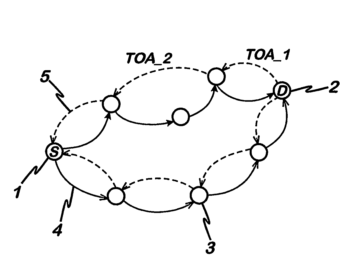
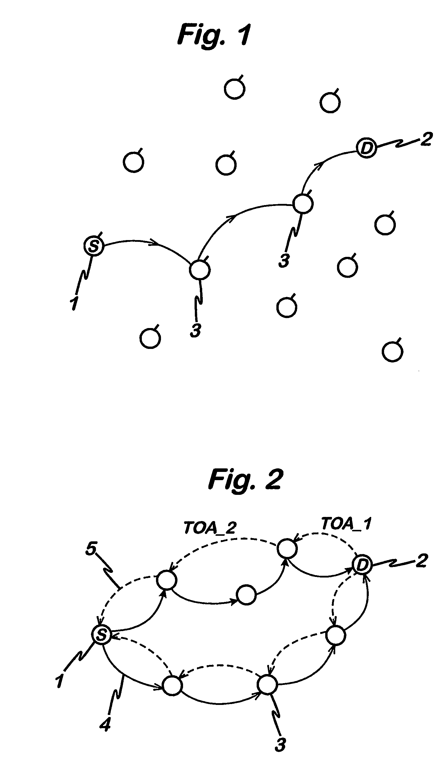
[0034]FIG. 1 shows an example of a mobile ad hoc network according to the present invention. The mobile ad hoc network will hereinafter be referred to as MANET, which is a popular abbreviation used in this field to indicate these types of networks. It can be seen that the MANET network is comprised of a plurality of network nodes 3, each node having at least one radio transceiver for transmitting and / or receiving from a neighbour node. FIG. 1 represents a snapshot of a MANET network at a particular instance in time, because by definition the ad hoc nature of such network means that the topology shown in FIG. 1 is expected to change dynamically over time. That is, the nodes 3 in a MANET network are free to move.

[0035]Data is transmitted across the network using a packet switched system where data packets are routed through a communications network on a “hop by hop” basis to reach their final destination. The Internet protocol (IP) is one embodiment of a protocol, which can be used to...


PUM


Abstract

A method of routing a message from a source node to a destination node in an adhoc wireless network comprising a plurality of nodes, comprising the steps of; transmitting a first message from the source node to the destination node, receiving said first message at said destination node, transmitting a second message from said destination node in response to the first message and, wherein at least one of said first message and said second message is sent between the source and destination nodes via a plurality of paths comprising at least one intermediate node, selecting a path for communication between the source node and the destination node using an indication of the time taken for at least one of said second and first messages to propagate between each node on each path.

Description

FIELD OF THE INVENTION[0001]The present invention relates to a method and apparatus for providing a routing mechanism in an ad-hoc network.BACKGROUND OF THE INVENTION[0002]FIG. 1 is a diagram of an ad hoc network. An ad hoc network comprises nodes, such as mobile stations that can communicate directly with each other, without the use of a centralised access point. In such a network all nodes behave as routers. Since the nodes are free to move randomly the topology of the network changes with time. Data from a source node (1) (the terminal that is sending data) is sent to a destination node (2) (the terminal that is receiving the data), via intermediate nodes which forward the data from the source node to the destination node. Determining the route by which data is sent from the source node to the destination node is achieved by selecting which intermediate nodes are used to forward the data. This is known as routing.[0003]Different routing protocols for ad hoc networks are currently...

Claims


Application Information

Patent Timeline
Patent Type & Authority Patents(United States)
IPC IPC(8): H04L12/28H04B7/26H04L1/16H04L45/121H04W40/00H04W40/02H04W40/08H04W40/10H04W40/12H04W40/14H04W40/20H04W40/24H04W84/18
CPCH04L45/121H04L45/26H04L45/70H04W40/02H04L1/16H04W40/08H04W40/10H04W40/12H04W40/14H04W40/20H04W40/246H04W84/18Y02B60/50Y02D30/70
Inventor NAGHIAN, SIAMAK
Owner MANITOBA UNIV OF THE
Learn More