Device and method for creating retinal fundus maps

a technology of retinal fundus and map, applied in the field of devices and methods for creating retinal fundus maps, can solve the problems of lack of credibility of matching, long processing time, and high computational load, and achieve the effect of convenient judgmen

Active Publication Date: 2011-12-06
KOWA CO LTD
View PDF2 Cites 10 Cited by
  • Summary
  • Abstract
  • Description
  • Claims
  • Application Information

AI Technical Summary

Benefits of technology

[0014]Besides, at the time of the matching processing, the probability distribution diagram is computed and obtained for the corner data image which shows the characteristic point data which are corner portions detected from blood vessel portions from the corner data image by convolving with a window function, and the matching processing between two or more fundus images is executed on the basis of the probability distribution diagram and corner data image by computing the matching probability score, so that computational volume for computing the matching probability score can be widely decreased in comparison with the correlation matching processing between pixels of original fundus images, and the processing in a short time is possible
[0033]According to this aspect of the invention, a gray image can be easily judged even if color / gray data are not stored at the time of obtaining fundus images.

Problems solved by technology

If photographic conditions (which may be changed according to a value of gamma, existence of optic disk, state of flare, or quantity of blood vessels) are not constant at the time of matching for blood vessel intersections, correct correspondence between the intersections is not ensured, and this matching lacks credibility.
Then, computational load is rather high, and it takes longer time for processing thereby.

Method used


Image

  • Device and method for creating retinal fundus maps
  • Device and method for creating retinal fundus maps
  • Device and method for creating retinal fundus maps

Examples


Embodiment Construction

[0055]An embodiment of the invention will now be explained, referring to appended figures.

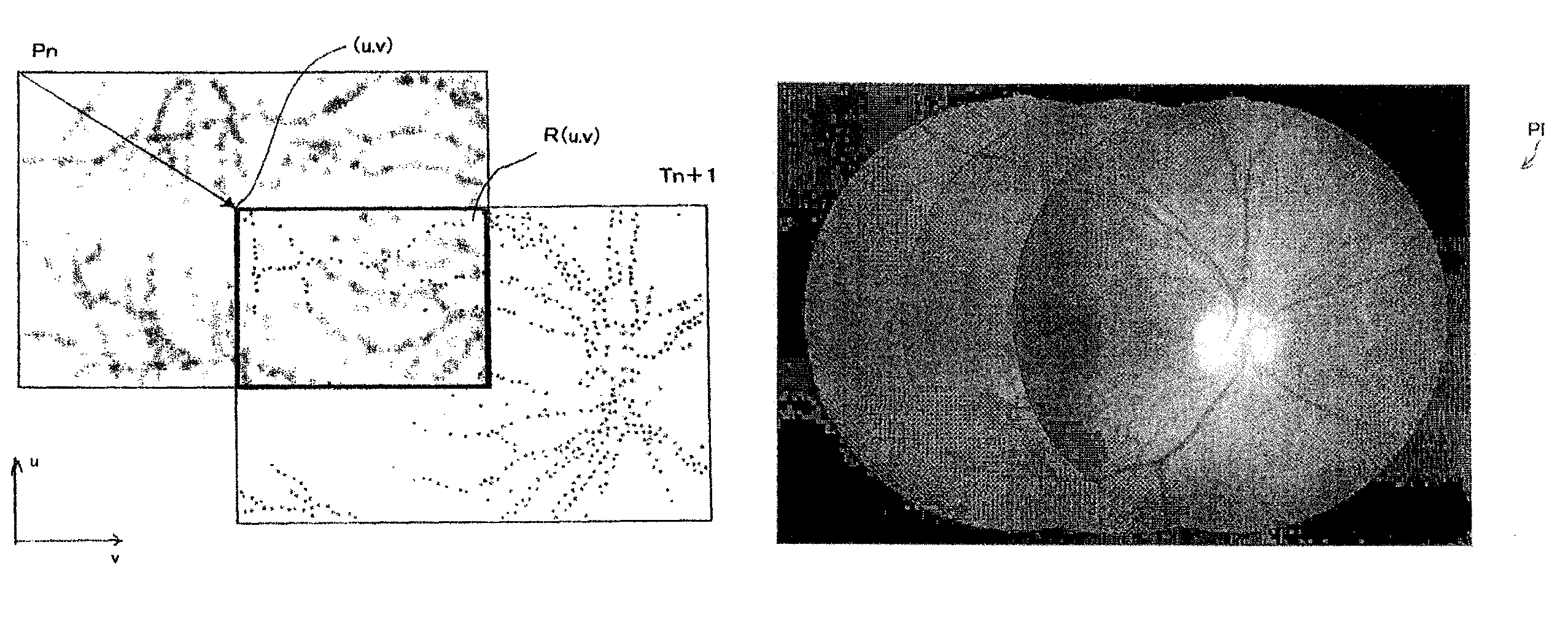
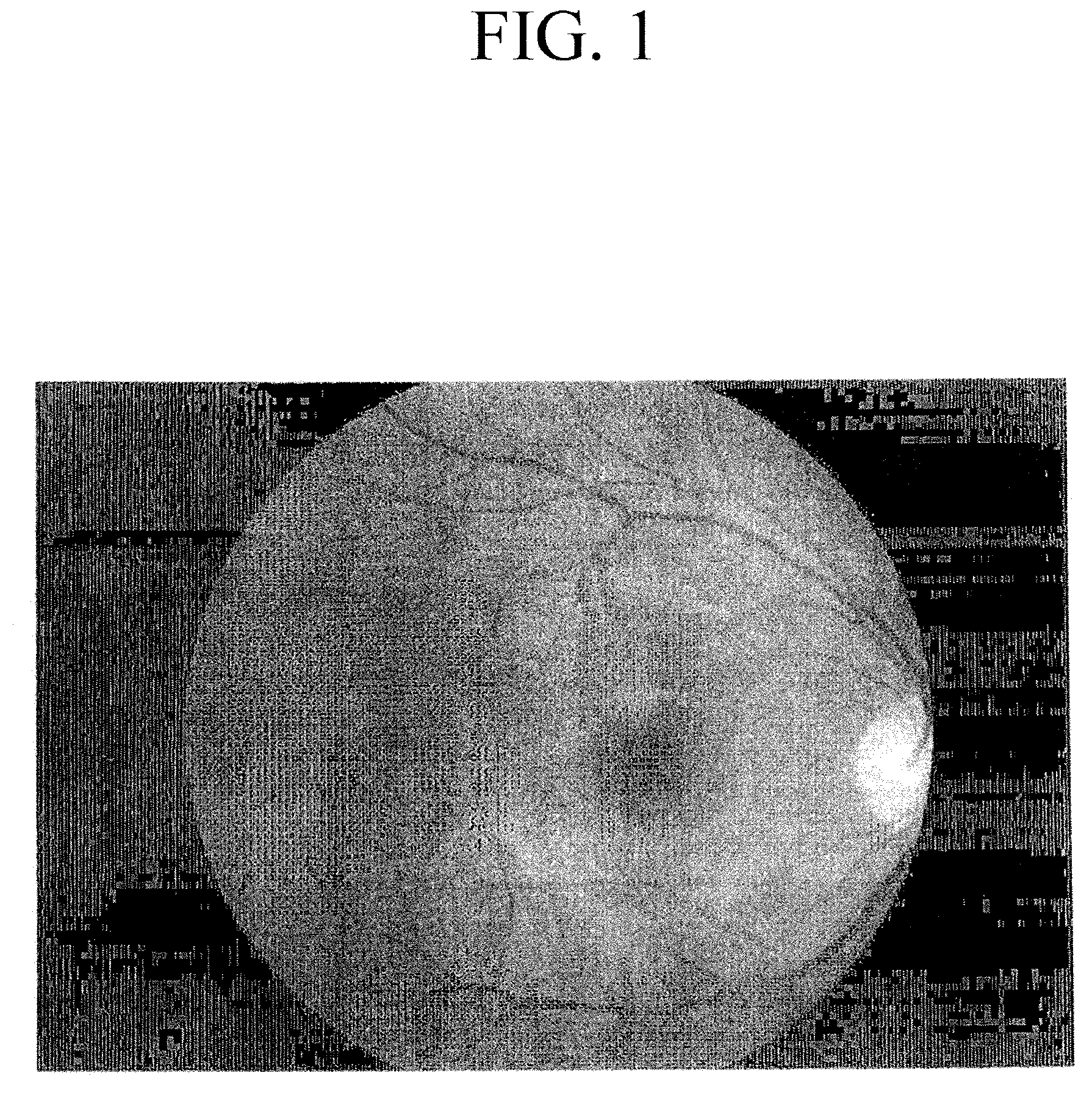
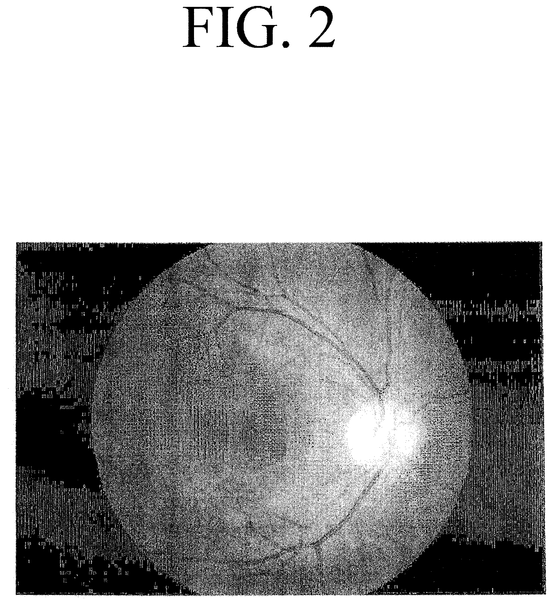
[0056]FIGS. 1 to 3 are views of a series of fundus images of the same eye to be examined, which are obtained by a fundus camera, FIG. 4 is an enlarged view of the fundus image, FIG. 5 is a view of the image after spatial frequency components lower than blood vessel components are extracted from the image of FIG. 4, FIG. 6 is a view of the image after the low spatial frequency components in FIG. 5 are removed from the image of FIG. 4, FIG. 7 is a view of the image after detecting corner characteristic points of blood vessels from the image of FIG. 6, FIG. 8 is an image of only the corner characteristic points after removing the original blood vessels image from the image of FIG. 7, FIG. 9 is an image which is converted from the image of the corner characteristic points of FIG. 8 into a probability distribution diagram, FIG. 10 is a view showing a routine of computing a probability score of match...


PUM


Abstract

A device has means for computing and obtaining blood vessel extraction images by extracting blood vessel portions from two or more fundus images, means for computing and obtaining a corner data image having corner portions of the blood vessel portions detected from the obtained blood vessel extraction image, means for computing and obtaining a probability distribution diagram for the corner data image by convolving the corner data image with a window function, means for computing a matching probability score when executing a matching processing between two or more fundus images on the basis of the probability distribution diagram corresponding to each fundus image obtained and the corner data image, and means for creating a retinal fundus map by superimposing two or more fundus images on the basis of the obtained matching probability score.

Description

CROSS-REFERENCE TO RELATED PATENT APPLICATIONS[0001]This application claims priority under 35 U.S.C. §119(a) to Japanese Patent Application No. 2007-290685, filed Nov. 8, 2007, the entirety of which is hereby incorporated by reference.BACKGROUND OF THE INVENTION[0002]The invention relates to a device and a method for creating retinal fundus maps by combining two or more retinal fundus images.[0003]In a previously known device for combining two or more retinal fundus images to create a retinal fundus map (retinal image montage), intersections between blood vessels which are shown in each fundus image are extracted as characteristic points, and correlation matching is executed on image data which are at a periphery of the intersections of blood vessels in two sheets of fundus images to find a pair having a common intersection, and two fundus images are superimposed on each other with the found intersection pair as a standard so as to create a retinal fundus map. Such technique is disc...

Claims


Application Information

Patent Timeline
Patent Type & Authority Patents(United States)
IPC IPC(8): G06K9/00G06V10/24
CPCA61B3/12G06K9/32G06T7/0028G06K2009/00932G06T7/33G06V40/14G06V10/24
Inventor SHINOHARA, TAKAO
Owner KOWA CO LTD
Why Eureka
Try Eureka