System and method for providing power management in a sensor network

a sensor network and power management technology, applied in the field of sensor networks, can solve the problems of difficult rechargeable batteries, critical power management, and impracticality for sensor networks with a large number of sensors

Inactive Publication Date: 2011-12-06
RPX CLEARINGHOUSE
View PDF4 Cites 37 Cited by
  • Summary
  • Abstract
  • Description
  • Claims
  • Application Information

AI Technical Summary

Problems solved by technology

Power management is a critical issue for sensing nodes in a sensor network.
With potentially hundreds to tens of thousands of sensing nodes in a sensor network changing batteries of sensing nodes or refreshing rechargeable batteries can pose a difficult challenge.
One such technique is to connect sensing nodes to regular electrical outlets using power plugs However, it is often impractical for sensor networks with a large number of sensors to be plugged into regular electrical outlets.
Not only does it restrict sensor placement, it limits use of existing outlets by other equipment.
Furthermore, dedicated wiring adds significant cost and may simply be impractical or undesirably expensive for retrofitting extensive sensor networks in existing buildings.
However for sensing nodes that must run for the majority of the time or for high performance sensing nodes, this technique does not help because the battery power of a sensing node may only last for a matter of hours before it runs out.
Furthermore, sensing nodes are used at less than full capabilities solely because of power limitations
This limitation puts restrictions on the placement of the sensing node, which could potentially affect sensor network performance.

Method used


Image

  • System and method for providing power management in a sensor network
  • System and method for providing power management in a sensor network
  • System and method for providing power management in a sensor network

Examples


Embodiment Construction

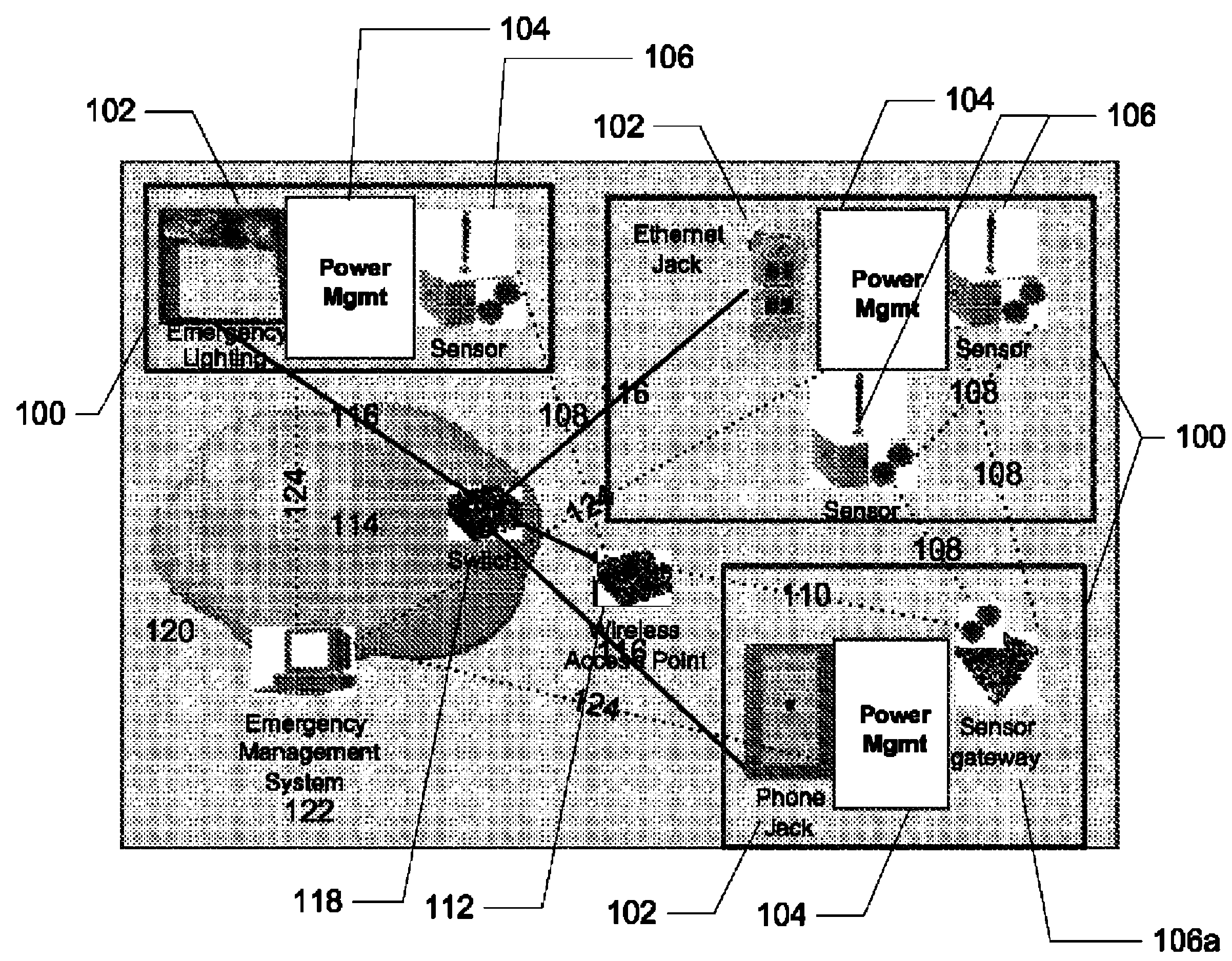
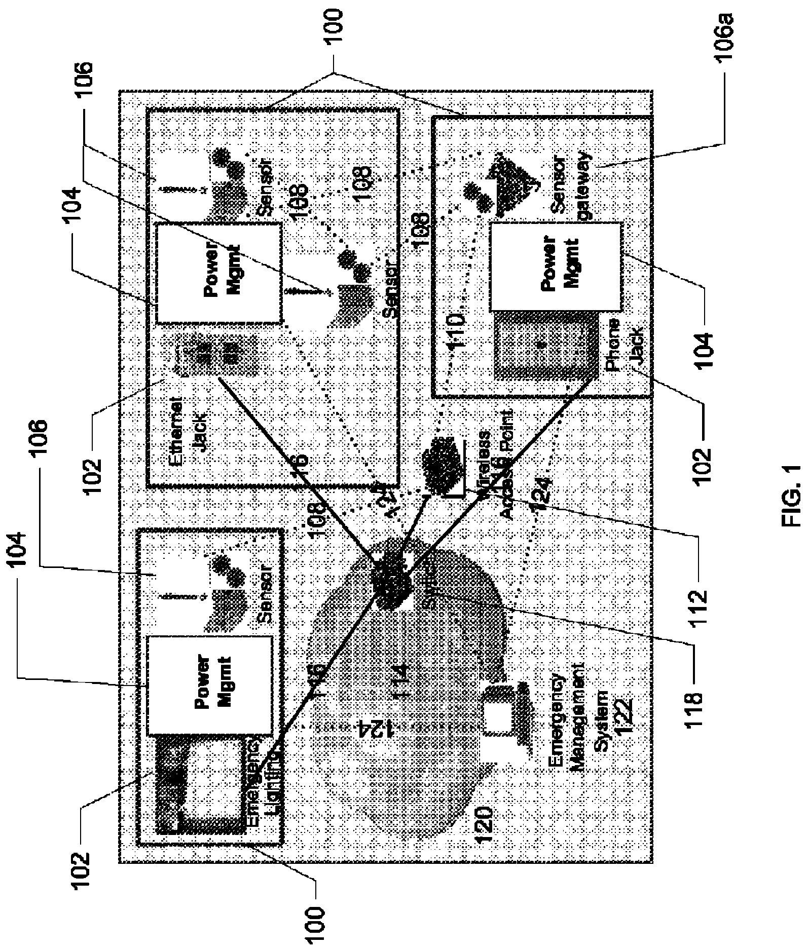
[0026]Referring to FIG. 1, which shows schematically a system for managing power of a sensor network according to an embodiment of the present invention, a sensor network 100 comprises a plurality of sensing nodes 106. For simplicity, only a few nodes are shown schematically in FIG. 1

[0027]The sensor network 100 may comprise a wide range of sensing nodes 106 such as stationary or mobile sensing nodes, where each node could be wired or wireless. Each sensing node may perform one or more distinct sensing activities such as sensing a particular physical, radiation, chemical or lighting presence, and may include RFID sensors. The sensing nodes 106 in the sensor network 100 are able to communicate with other sensing nodes in the sensor network 100 via wired and or wireless links 108 according to well known sensor network routing protocols, such as flooding, SPIN and LEACH.

[0028]As in a conventional sensor network, the sensor network 100 is structured according to known sensor network arc...


PUM


Abstract

The present invention relates to a system and method for providing power management to sensing nodes in a sensor network. A system may include a plurality of sensing nodes, each sensing node connected through a power management device to an external power source, such as a powered node of another network, for managing power from the external power source to the sensing node. Beneficially, a plurality of power management devices allow for a sensor network of fixed or mobile wireless sensing nodes or sensor gateways to make use of power from an external source such as an another network e.g. an existing emergency lighting system or other similar powered building system. Thus for example, a sensor or group of sensing nodes and their associated power management devices may be integral with or co-located in proximity to powered nodes of these other networks. An intelligent power management device connected to at least one of the sensing nodes may provide for power policy management to sensing nodes based on monitoring power conditions such as available power, power level status, and information obtained from the sensing nodes indicative of network conditions, detecting a change therein, and regulating power to the sensing node depending on the change.

Description

FIELD OF INVENTION[0001]The present invention relates to sensor networks, and in particular, to a system and method for providing power management to sensing nodes in a sensor network.BACKGROUND[0002]Power management is a critical issue for sensing nodes in a sensor network. Since many sensing nodes are powered by batteries, it is apparent that for every function they perform their energy supply decreases. With potentially hundreds to tens of thousands of sensing nodes in a sensor network changing batteries of sensing nodes or refreshing rechargeable batteries can pose a difficult challenge. As such, sensing nodes typically use one or more techniques to mitigate this problem.[0003]One such technique is to connect sensing nodes to regular electrical outlets using power plugs However, it is often impractical for sensor networks with a large number of sensors to be plugged into regular electrical outlets. Not only does it restrict sensor placement, it limits use of existing outlets by ...

Claims


Application Information

Patent Timeline
Patent Type & Authority Patents(United States)
IPC IPC(8): G05B11/01
CPCG01D21/00H02J1/00H04L67/125Y04S40/18
Inventor VEZZA, BRIANFELSKE, KENTGRAVES, ALANWATKINS, JOHNDUXBURY, GUYCHMARA, TOMFITCHETT, JEFF
Owner RPX CLEARINGHOUSE
Why Eureka
Try Eureka