Component life indicator

a technology of component life and indicator, applied in the direction of instruments, nuclear elements, nuclear engineering, etc., can solve the problems of component failure before scheduled maintenance, shortening the actual work life of the component, and seldom matching the actual work life of the design component li

Active Publication Date: 2011-12-06
CATERPILLAR INC
View PDF34 Cites 15 Cited by
  • Summary
  • Abstract
  • Description
  • Claims
  • Application Information

AI Technical Summary

Problems solved by technology

Accordingly, the actual work life of a component seldom matches the designed component life.
Failure to recognize that the component has a shorter actual work life can result in failure of the component before scheduled maintenance is performed.
Operating the component until it fails often causes secondary failures of other components that are dependent upon the failed component.
Further, such failures are often unpredictable in time, and may require performing maintenance in places at the work site where the work machine is not easily accessible, or the work machine may be in the path of other work machines.
Thus, failure of a single component may cause increased down time and higher operating expenses for the overall operation.
Accordingly, performing the scheduled maintenance may be wasteful because the components do not yet need to be serviced.
However, the '284 patent does not disclose a system for monitoring the actual work life of a machine component.

Method used


Image

  • Component life indicator
  • Component life indicator
  • Component life indicator

Examples


Embodiment Construction

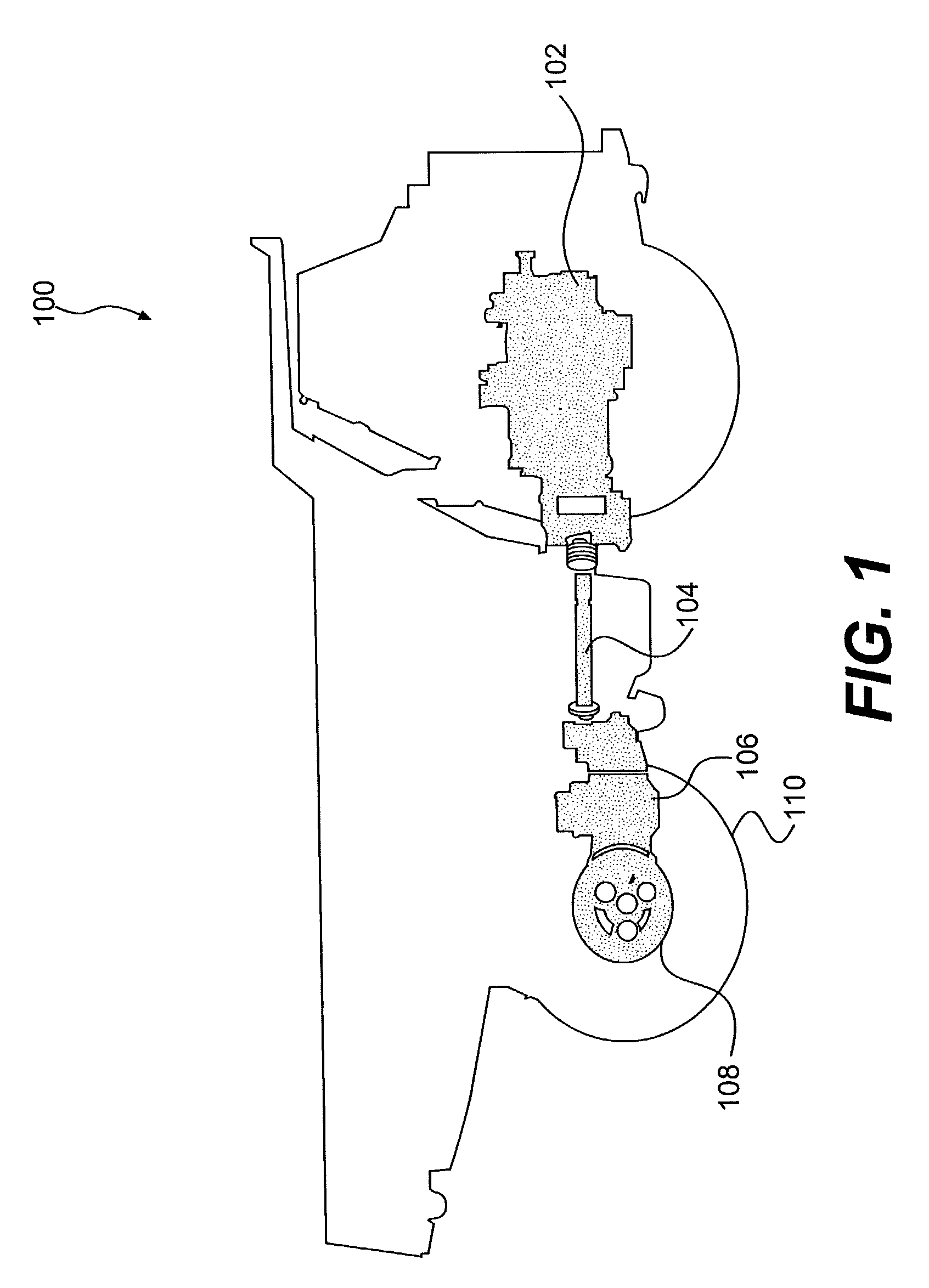
[0022]FIG. 1 is a diagram of an exemplary embodiment of a silhouette of a work machine 100 showing exemplary components that may be monitored by a component life indicator. In the exemplary embodiment shown, work machine 100 is a dump truck. However, the work machine 100 could be any work machine, such as for example, a tractor, a loader, an earth mover, an excavator, or other work machine, as would be apparent to one skilled in the art. The work machine 100 is powered by an engine 102 mechanically driving a drive shaft 104 which extends from the engine 102 to a transmission 106. The transmission 106 is mechanically connected to a final drive assembly 108. The final drive assembly 108 is mechanically connected to rear wheels 110 of the work machine 100. This driving system of the work machine 100 could be any operable configuration, as would be apparent to one skilled in the art. Moreover, while a work machine is illustrated, the present disclosure has potential applicability to oth...


PUM


Abstract

A life indicator for a component of a machine is disclosed. The life indicator includes at least one sensor operably associated with the machine and configured to sense a property associated with the machine. The sensor is configured to output the sensed property as a data signal. The life indicator also includes a memory element having a first data structure that determines a damage factor for the component of the machine based at least in part on the data signal received from the at least one sensor. A processor executes the first data structure to determine the damage factor.

Description

TECHNICAL FIELD[0001]This disclosure relates generally to a component life indicator. More specifically, this disclosure relates to a component life indicator for monitoring the effects of operating conditions on the work life of a machine component.BACKGROUND[0002]A typical work machine, such as, for example, a tractor, dozer, loader, earth mover or other such piece of equipment, has a designed work life. The designed work life of the work machine is determined, in part, by the designed work life of each individual component making up the work machine. However, the actual work life of a given component, and thus the actual life of the work machine itself, may vary from machine to machine based on use stresses to which the work machine is subjected. Use stresses that affect the work life of a work machine may include, for example, operating conditions, road layout, weather conditions, road conditions, loading practices, and efficiencies.[0003]The designed work life of a component co...

Claims


Application Information

Patent Timeline
Patent Type & Authority Patents(United States)
IPC IPC(8): G06F17/18G06F11/30G01B3/44G21C17/00G01B3/52G07C3/00
CPCG07C3/00
Inventor SUZUKI, JINHINTON, DAVID RANDALGANNON, JULIE A.GREMBOWICZ, CONRAD GENE
Owner CATERPILLAR INC
Why Eureka
Try Eureka