Enhanced static-dynamic pressure transducer suitable for use in gas turbines and other compressor applications

a static-dynamic, transducer technology, applied in the direction of fluid pressure measurement by mechanical elements, instruments, measurement devices, etc., can solve the problems of reducing the resolution or the sensitivity of the sensor at the end of the span is reduced, and the thickness of the diaphragm is not easy to d

Active Publication Date: 2011-12-13
KULITE SEMICON PRODS
View PDF29 Cites 10 Cited by
  • Summary
  • Abstract
  • Description
  • Claims
  • Application Information

AI Technical Summary

Problems solved by technology

Thick diaphragms, however, have poor sensitivity to low pressures.
A pressure transducer adapted to measure relatively large pressures typically suffers from relatively poor resolution or sensitivity when measuring relatively low pressures because, as a span of the sensor increases, the resolution or sensitivity of that sensor at the ends of the span decreases.
Due to the properties of pressure sensors, it is extremely difficult to measure both static pressure (Ps) and dynamic pressure (Pd) unless one uses a thick diaphragm for high static pressure (Ps) in conjunction with a thin diaphragm for low dynamic pressure (Pd) fluctuations.
However, a thin diaphragm will rupture when exposed to high static pressure (Ps).
However, if static (Ps) and dynamic pressures (Pd) are equal on both sides of the diaphragm, the sensor will be unable to make a pressure reading.

Method used


Image

  • Enhanced static-dynamic pressure transducer suitable for use in gas turbines and other compressor applications
  • Enhanced static-dynamic pressure transducer suitable for use in gas turbines and other compressor applications
  • Enhanced static-dynamic pressure transducer suitable for use in gas turbines and other compressor applications

Examples


Embodiment Construction

[0024]Referring now to the figures, wherein like reference numerals represent like parts throughout the several views, exemplary embodiments of the present invention will be described in detail. Throughout this description, various components may be identified having specific values or parameters; however, these items are provided as exemplary embodiments. Indeed, the exemplary embodiments do not limit various aspects and concepts of the present invention as many comparable parameters, sizes, ranges, and / or values may be implemented.

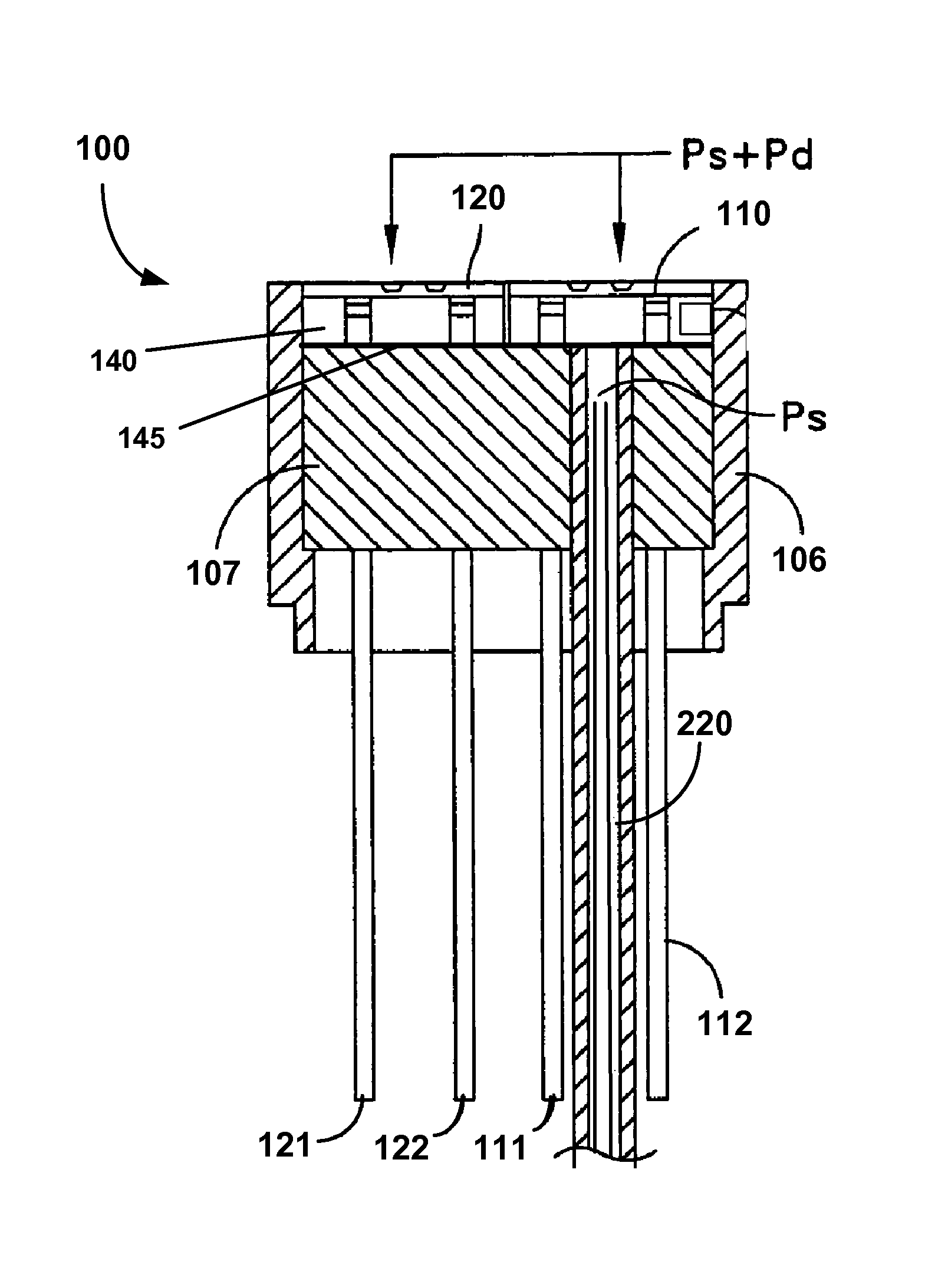
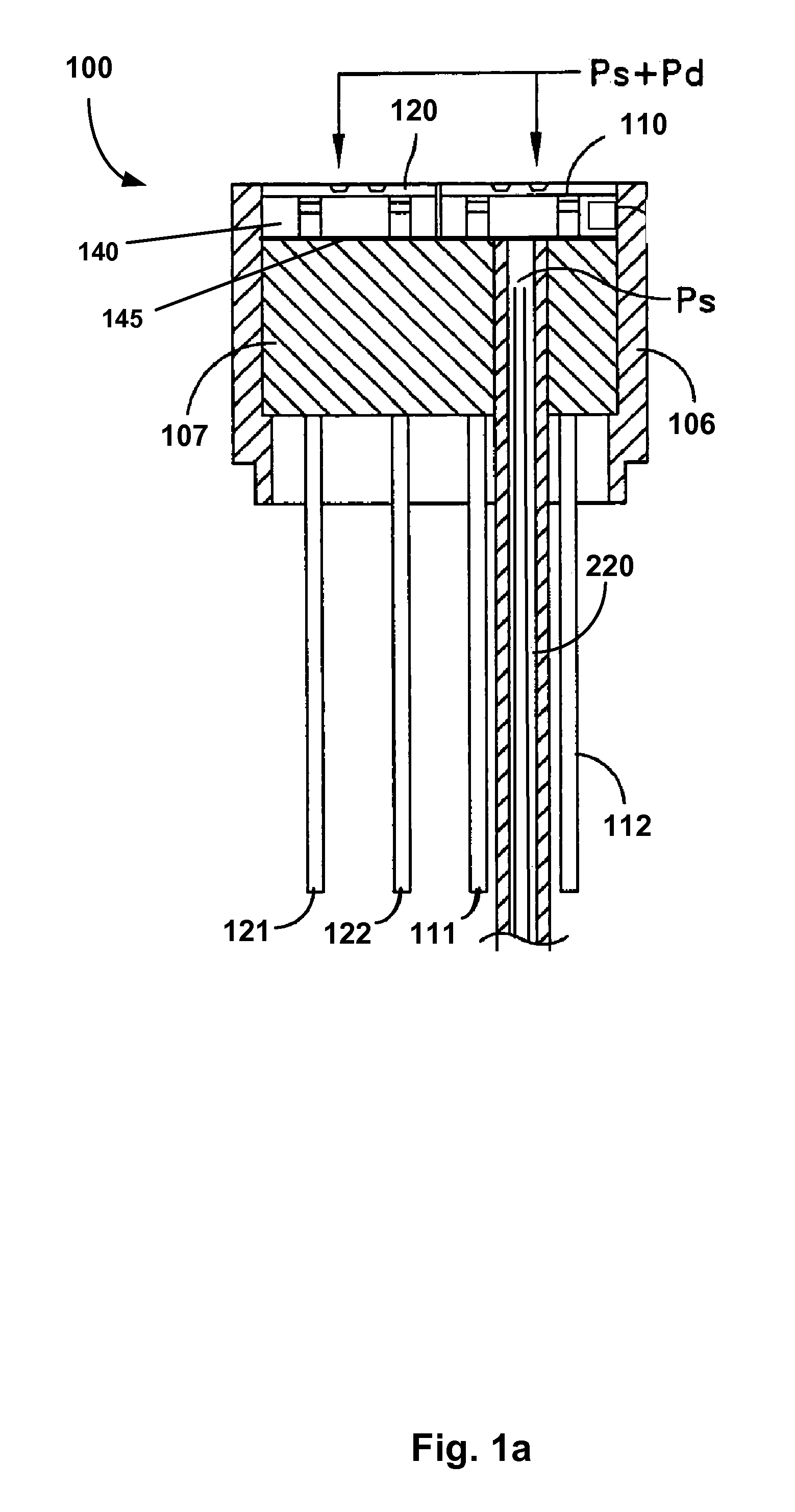
[0025]FIG. 1a illustrates a portion of a static-dynamic pressure transducer 100 (referred to herein as static-dynamic pressure transducer, static-dynamic transducer, pressure transducer, sensor, or transducer) in accordance with an exemplary embodiment of the invention. The pressure transducer 100 may comprise two leadless piezoresistive sensors, a dynamic pressure sensor 110 and a static pressure sensor 120 disposed within a header 106. The sensors 110 ...


PUM

PropertyMeasurementUnit
pressuresaaaaaaaaaa
temperaturesaaaaaaaaaa
pressureaaaaaaaaaa

Abstract

A filter assembly for use with a static-dynamic piezoresistive pressure transducer that measures low amplitude, dynamic pressure perturbations superimposed on top of a high static pressure through the implementation of a low-pass mechanical filter assembly is disclosed. The filter assembly may comprise a dual lumen reference tube and a removable filter subassembly further comprising a porous metal filter and narrow diameter tube. The transducer, which may be capable of operating at ultra-high temperatures and in harsh environments, may comprise of a static piezoresistive pressure sensor, which measures the large pressures on the order of 200 psi and greater, and an ultrasensitive, dynamic piezoresistive pressure sensor which may capture small, high frequency pressure oscillations on the order of a few psi or less. The filter assembly may transmit static pressure to the back of the dynamic pressure sensor to cancel out the static pressure present at the front of the sensor while keeping dynamic pressure from reaching the back of the sensor. In this manner, the filter assembly enables the transducer to accurately read dynamic pressure in the presence of high static pressure without rupturing the thin diaphragm of the dynamic pressure sensor.

Description

FIELD OF THE INVENTION[0001]The invention relates to pressure transducers for measuring low dynamic pressures (Pd) in the presence of high static pressures (Ps), and more particularly to improved low-pass filter structures employed with such transducers.BACKGROUND[0002]During the testing of jet engines and in many other turbine and high pressure environments, it is often desirable to measure both the static pressure (Ps) and the dynamic pressure (Pd). The static pressure (Ps), in most instances, is usually very high (200 psi) and the dynamic pressure (Pd) is much lower. Accordingly, the dynamic pressure (Pd) may typically be 20 times less than the static pressure (Ps). Additionally, the dynamic pressure (Pd) is also associated with a distinct frequency which occurs at a relatively high rate, for example 5000 cycles / second or greater. To measure static pressure (Ps), one requires a transducer with a relatively thick diaphragm so that it can withstand the high static pressure (Ps). Th...

Claims


Application Information

Patent Timeline
Patent Type & Authority Patents(United States)
IPC IPC(8): G01L13/02
CPCG01L9/0052G01L19/0609G01L15/00G01L19/00
Inventor KURTZ, ANTHONY D.KURTZ, LEGAL REPRESENTATIVE, NORAKOCHMAN, BOAZHURST, ADAMSHANG, TONGHUO
Owner KULITE SEMICON PRODS
Why Eureka
Try Eureka