
Method for load limiting in drive systems for aircraft high lift systems
a technology of drive system and load limit, which is applied in the direction of automatic actuation, process and machine control, instruments, etc., can solve the problems of increasing the mass and operating cost of aircraft equipped, and achieve the effect of limiting fault-dependent overload and reducing the mass and operating cost of the system
- Summary
- Abstract
- Description
- Claims
- Application Information
AI Technical Summary
Benefits of technology
Problems solved by technology
Method used
Image

Examples
Embodiment Construction
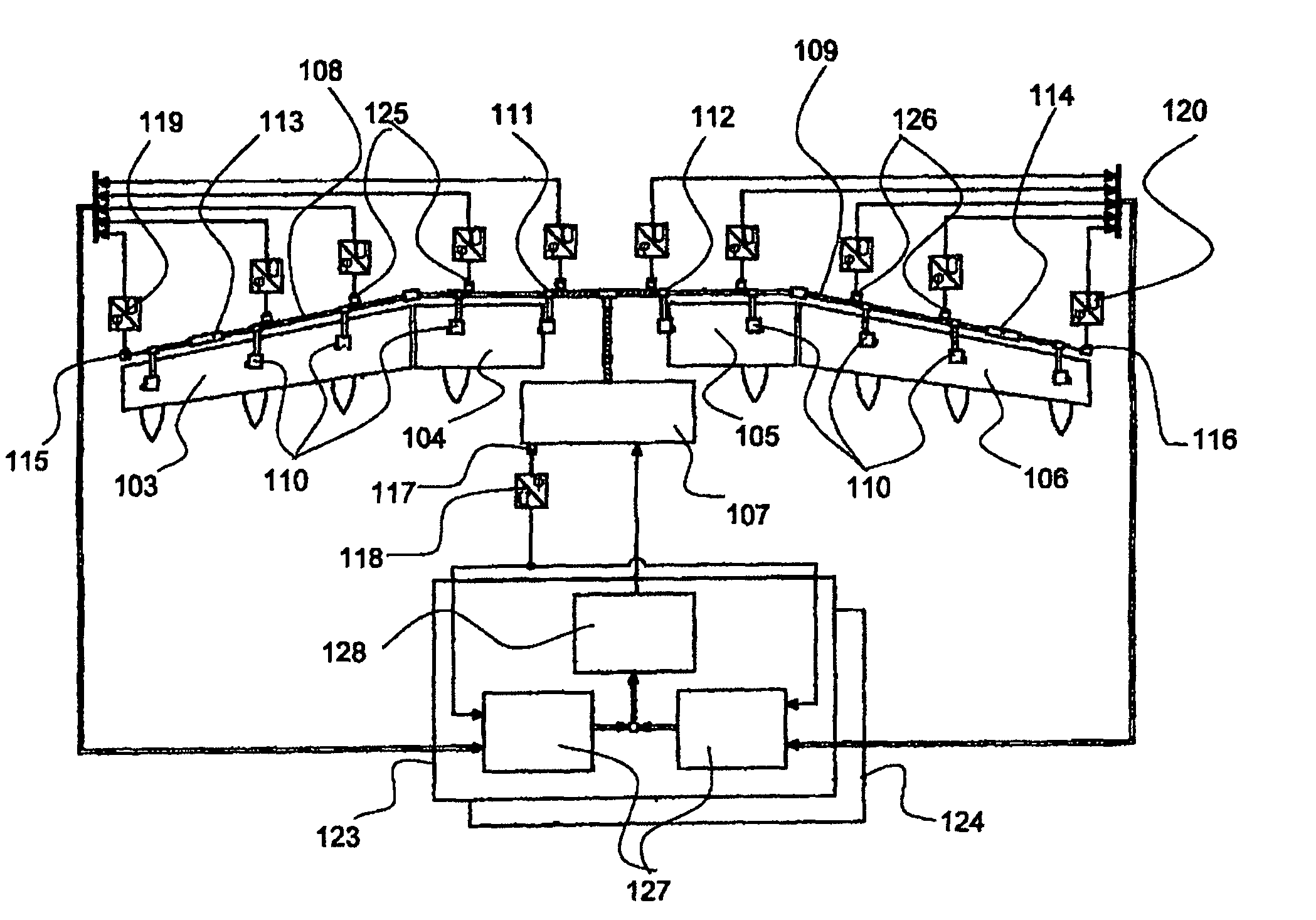
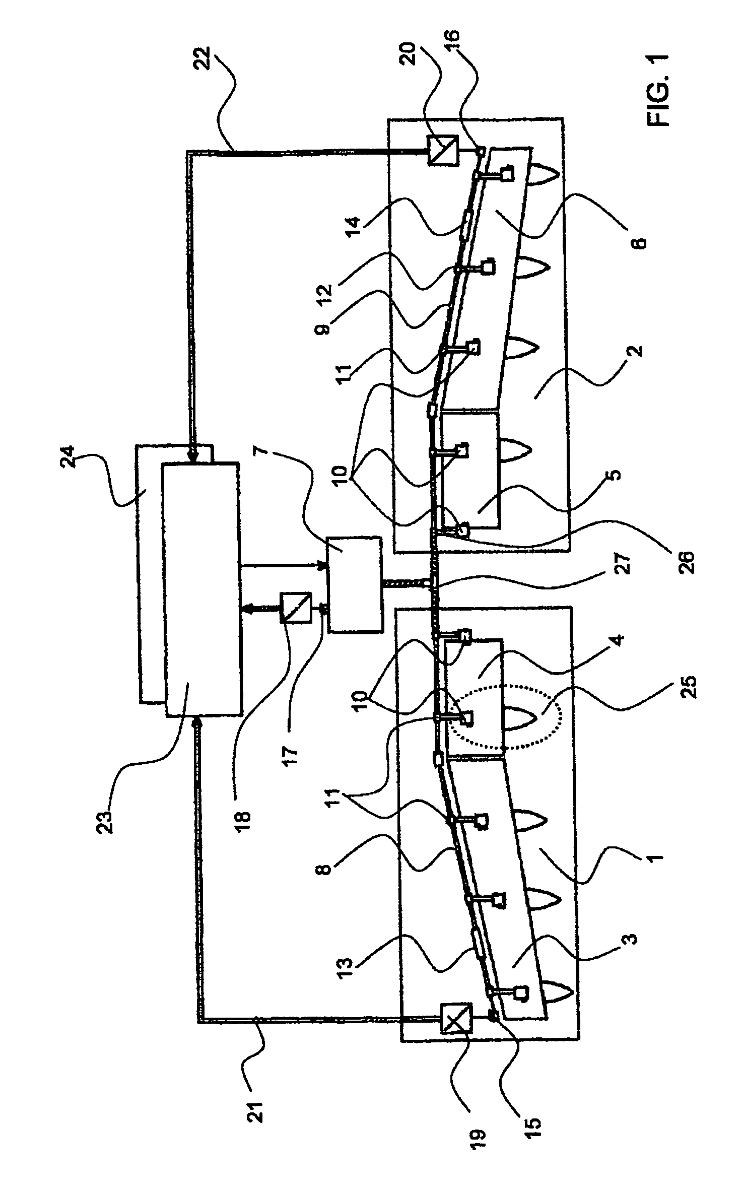
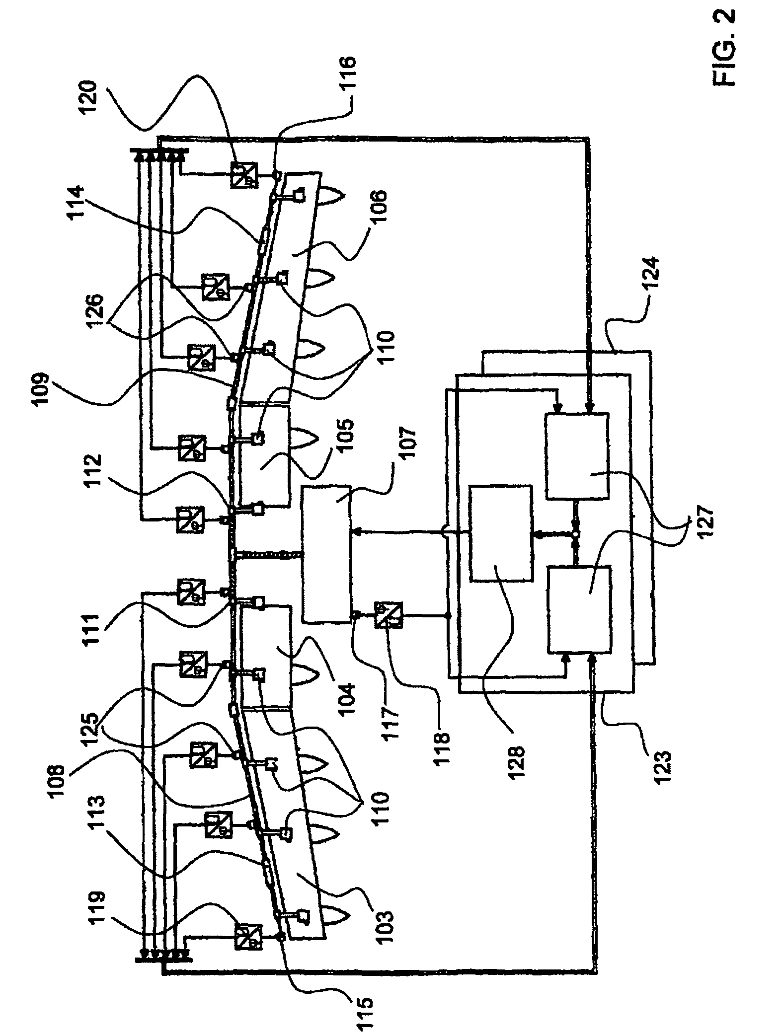
[0012]The drive system as illustrated in FIG. 1 for landing flaps is equipped with electronically controlled overload protection rather than with a conventional mechanical load limiter. In this case, the drive system comprises a port and a starboard subsystem 1, 2, which are respectively used to drive two high-lift flaps 3, 4 and 5, 6 which are arranged on the trailing edges of the wing, with the two subsystems 1, 2 being designed to be symmetrical with respect to one another. The mechanical power which is required to position the flaps 3 to 6 is produced by a central drive unit 7 whose power can be controlled in a highly dynamic manner, and is in each case passed via a drive train 8, 9, respectively, to a series of mechanical actuators 10 in the two wings.
[0013]These in each case include branching transmissions, inter alia 11, 12. The individual drive stations 25 are connected to the drive train 8 by means of the respectively associated branching transmissions 11. Hydraulically ope...
PUM
 Abstract
Description
Claims
Application Information