Linear motor with force ripple compensation

a linear motor and ripple compensation technology, applied in the direction of dynamo-electric machines, electrical apparatus, magnetic circuits, etc., can solve the problems of motor not having a symmetrically induced voltage, uneven running and tracking errors in machining processes, and reducing cogging forces, so as to reduce electromotive forces. symmetrize the effect of force ripple compensation

Active Publication Date: 2011-12-13
SIEMENS AG
View PDF26 Cites 9 Cited by
  • Summary
  • Abstract
  • Description
  • Claims
  • Application Information

AI Technical Summary

Benefits of technology

[0007]The object of the present invention is therefore to develop a linear motor of the kind describe...

Problems solved by technology

For constructional reasons, permanently excited linear motors have force variations which have an adverse effect on even running and dynamics.
This results in vibrations, uneven running and tracking errors in machining processes.
This results in the motor not having a symmetrically induced voltage and, an additional current-dependen...

Method used


Image

  • Linear motor with force ripple compensation
  • Linear motor with force ripple compensation
  • Linear motor with force ripple compensation

Examples


Embodiment Construction

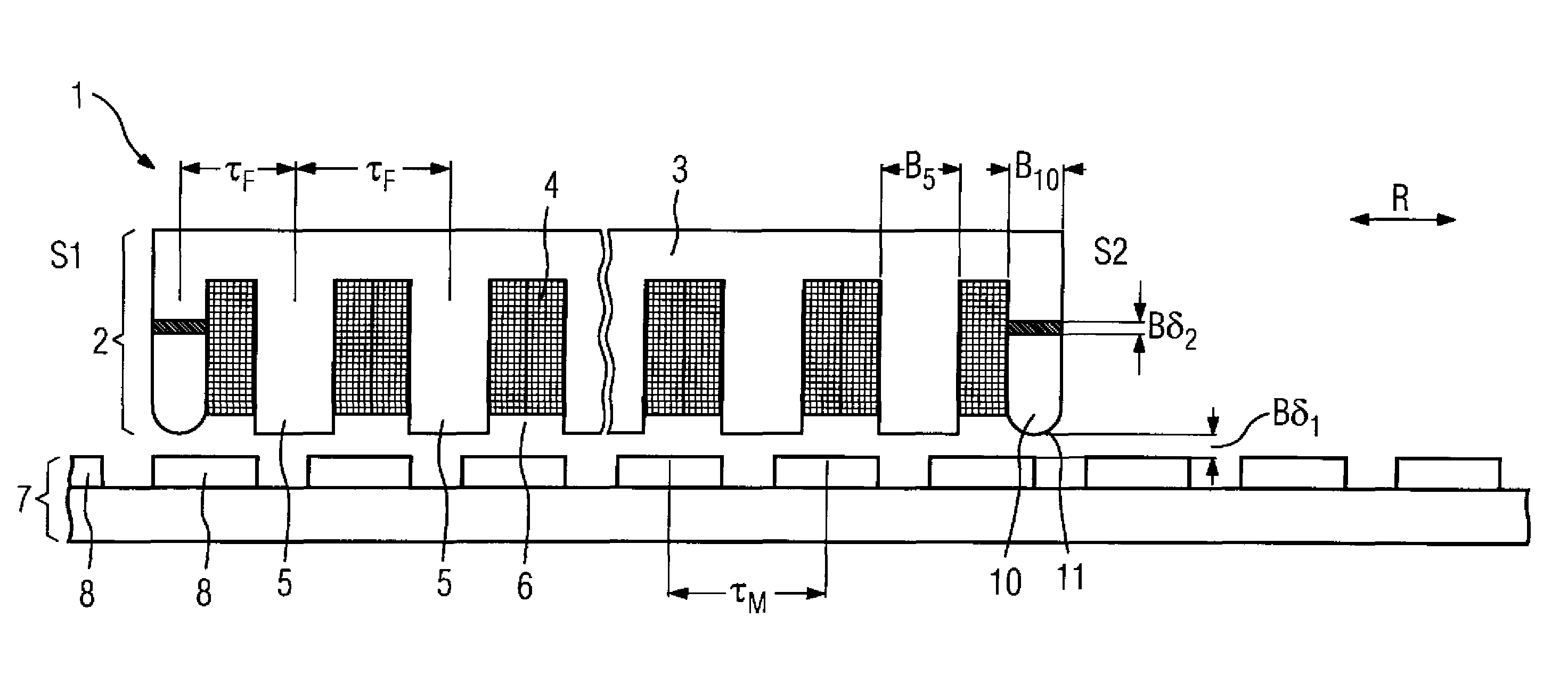
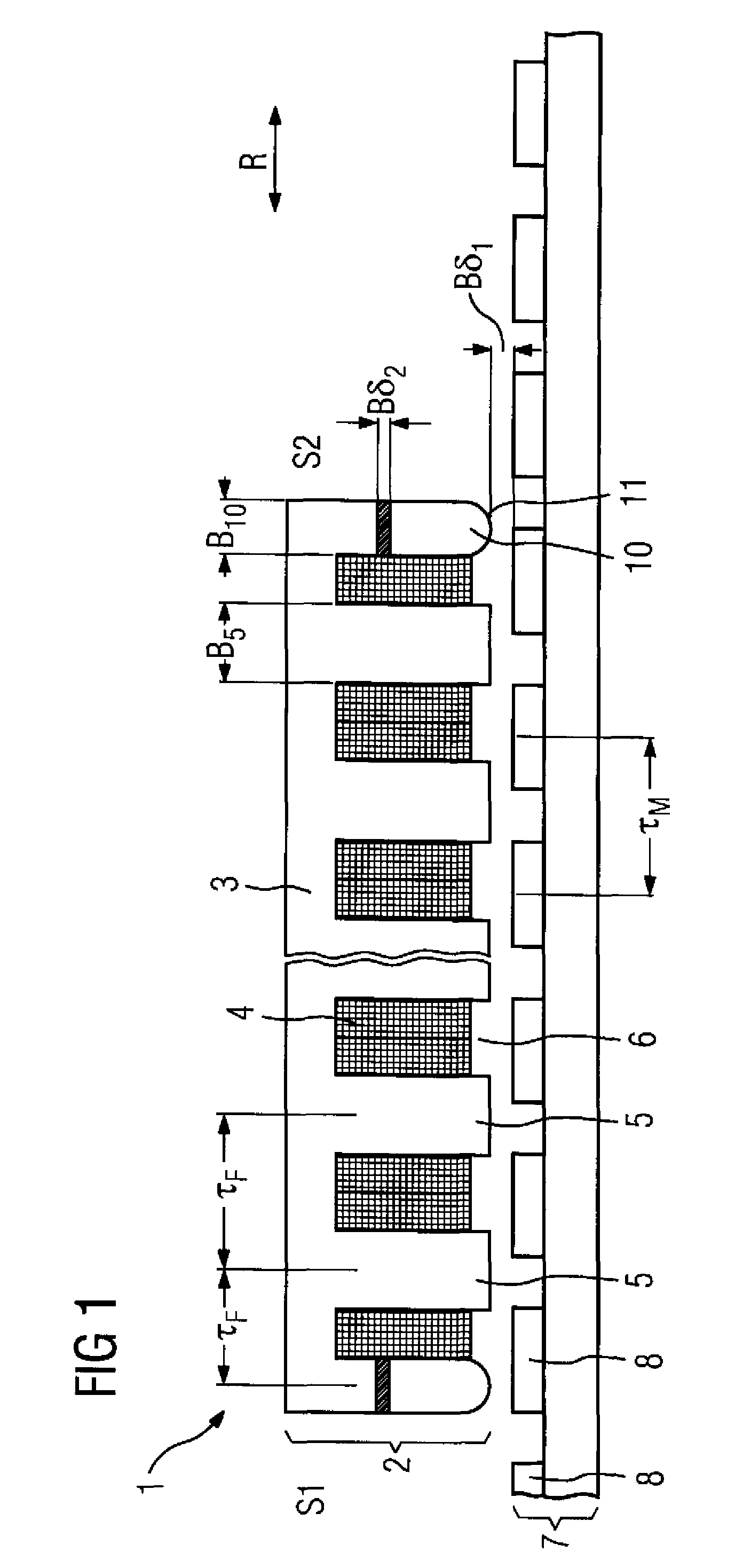
[0054]FIG. 1 shows a first embodiment of a linear motor 1 according to the invention with a first arrangement of a flux guiding element 10. FIG. 1 shows a side view of a synchronous linear motor 1 shown in principle, which has one or more laminated cores 3, the respective laminations of which are stacked parallel to the plane of the drawing and which form the primary component 2. The direction of motion of the linear motor 1 is shown by the arrow R. The primary component 2 also has the coils 4. The coils 4 encompass the teeth 5 of the primary component 2 in such a way that different coils 4 are located in one slot 6. Furthermore, the linear motor 1 has the secondary component 7 with the permanent magnets 8. The secondary component 7 is positioned on a machine bed which is not shown in more detail. The permanent magnets 8 are arranged with the pole pitch τM. The pole pitch τM can however also be formed by electrical excitation of an excitation winding arranged in the secondary compon...


PUM


Abstract

The invention relates to a primary component (2) for an electric motor (1), said primary component (2) being formed from at least one bundle of laminations (3) and comprises at least one flux guiding element (10) on one or both front faces (S1, S2) to reduce the ripple effect, said primary component (2) being separated from a secondary component (7) by a first air gap (δ1). The primary component (2) has at least one section (δ2) in the region of the flux guiding element (10), said section (δ2) being electrically non-conducting (Kel=0) and having a negligibly low magnetic permeability (μr≅1).

Description

BACKGROUND OF THE INVENTION[0001]The invention relates to a primary component for an electric machine, the primary component being formed from at least one laminated core and having at least one flux guiding element on one or both front faces to reduce the force ripple. Furthermore, the invention relates to a linear motor with a primary component of this kind.[0002]Linear motors have a primary component and a secondary component. The secondary component in particular is located opposite the primary component. The primary component is designed for energizing with electric current. The secondary component has permanent magnets or energizable windings for example. Both the primary component and the secondary component have active magnetic means for generating magnetic fields.[0003]For constructional reasons, permanently excited linear motors have force variations which have an adverse effect on even running and dynamics. The force variations are due in part to smaller induced voltages ...

Claims


Application Information

Patent Timeline
IPC IPC(8): H02K41/03H02K41/02
CPCH02K41/031H02K29/03H02K1/148H02K2201/03H02K2213/03
Inventor JAJTIC, ZELJKOVOLMERT, CHRISTIAN
Owner SIEMENS AG
Why Eureka
Try Eureka