
Communication device and semiconductor chip

a technology of communication device and semiconductor chip, which is applied in the direction of instruments, computers, and antennas, can solve the problems of increasing the length of the wiring, complicated structure, and difficulty in realizing the information transmission between the semiconductor chip with high speed and low electric power, and achieve the effect of reducing the electromotive for

Inactive Publication Date: 2012-12-20
PS4 LUXCO SARL
View PDF6 Cites 15 Cited by
  • Summary
  • Abstract
  • Description
  • Claims
  • Application Information

AI Technical Summary

Benefits of technology

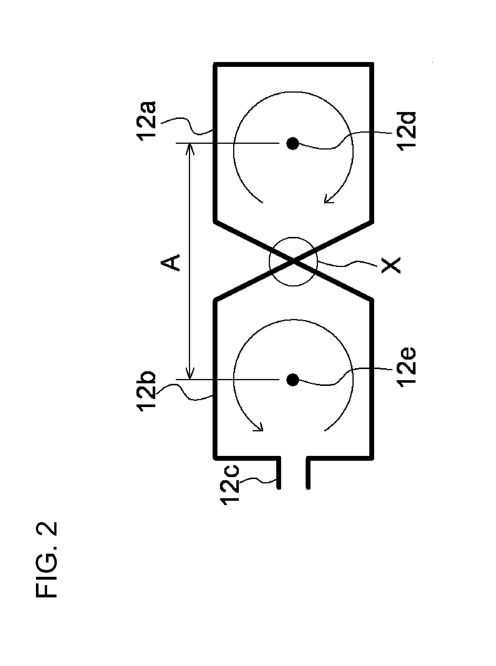
[0015]According to a second aspect of the disclosure, there is provided a semiconductor chip. The semiconductor chip operates by receiving lines of magnetic force. The semiconductor chip comprises a first loop that generates electromotive force in a predetermined direction when receiving the lines of magnetic force in a first direction, and a second loop which is electrically connected with the first loop so as to generate electromotive force in an opposite direction to the first loop when receiving the lines of magnetic force in the first direction on an operation and to decrease the electromotive force generated in the first loop.

Problems solved by technology

In the wire bonding method, a structure becomes complicated, and it is difficult to realize the information transmission between the semiconductor chips with high speed and low electric power.
When a plurality of the semiconductor chips are stacked to be packaged, for example, especially in a case of an SSD (Solid-State Drive) for large capacity of a semiconductor memory device and the like, positions of bonding pads are limited to the peripheral regions of the semiconductor chips.
Therefore, the length of the wiring is increased, and the information transmission takes a time and the power loss occurs.
However, this means makes the manufacturing process complicated.
On the other hand, there are three problems in the signal transmission of the magnetic coupling.
Secondly, if strong magnetic field is given from the exterior, a large signal is input to an input circuit, bringing out saturation of the circuit, and it takes a time for recovery.
In a worse case, the input circuit will be destroyed by an excessive input.
Thirdly, a side channel attack, that is, stealing information in a semiconductor device by detecting a weak radio wave that escapes from the magnetic coupling portion to the exterior, becomes amenable.
Although a method of forming a magnetic shield by being surrounded by a material having high magnetic permeability such as Permalloy is considered as a means for preventing information leakage and illicit access, the cost is increased as compared with a plastic package.
If the magnetic shield is removed, the information leakage and illicit access can not be prevented.

Method used


Image

  • Communication device and semiconductor chip
  • Communication device and semiconductor chip
  • Communication device and semiconductor chip

Examples


Embodiment Construction

[0029]The disclosure will be now described herein with reference to illustrative exemplary embodiments. Those skilled in the art will recognize that many alternative exemplary embodiments can be accomplished using the teachings of the present disclosure and that the disclosure is not limited to the exemplary embodiments illustrated for explanatory purposes.

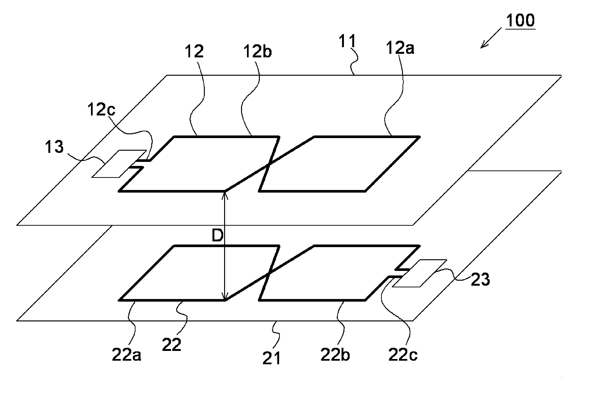
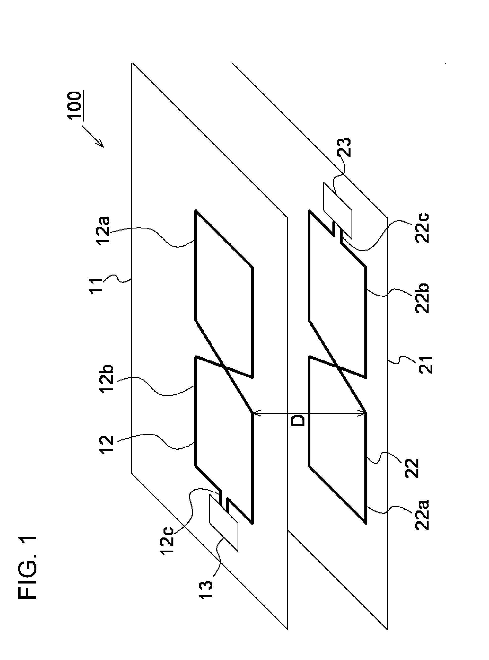
[0030]A communication device and electronic device according to a first exemplary embodiment of the present disclosure will be explained. FIG. 1 illustrates a diagram of the electronic device according to the first exemplary embodiment of the present disclosure. FIG. 2 illustrates a schematic top view of an antenna illustrated in FIG. 1. FIG. 3 illustrates a schematic side view of the antenna illustrated in FIG. 1.

[0031]The electronic device 100 comprises a first electronic component 11 and a second electronic component 21. A semiconductor device may be given as an example of the electronic device 100. In this example, stacked sem...


PUM


Abstract

A device includes a first substrate that has a first antenna having a first loop and second loop that form loop shapes viewed in a planar projection; and a second substrate that has a second antenna having a third loop and fourth loop that form loop shapes viewed in the planar projection. The first substrate and the second substrate are disposed so that the first antenna and the second antenna face each other. At least when the first substrate and the second substrate operate, the first antenna and the second antenna are in a state that the first antenna and the second antenna are capable of being magnetically coupled.

Description

TECHNICAL FIELD[0001]This application is based upon and claims the benefit of the priority of Japanese patent application No. 2011-134903, filed on Jun. 17, 2011, the disclosure of which is incorporated herein in its entirety by reference thereto.[0002]The present disclosure relates to a communication device using magnetism and, in particular, a communication device applicable to communication between semiconductor chips. The present disclosure also relates to an electronic device comprising the communication device.BACKGROUND[0003]Recently, wire bonding has been used for connection between semiconductor chips in one semiconductor package, for example, the connection between the semiconductor device of an MPU (Micro Processor Unit) and the semiconductor device of a DRAM (Dynamic Random Access Memory), a flash memory or the like.[0004]As information communication other than the wire bonding, information communication using magnetic coupling has been proposed (Non-Patent Document 1: N...

Claims


Application Information

Patent Timeline
Patent Type & Authority Applications(United States)
IPC IPC(8): H01Q21/00H01Q7/06H01Q7/00
CPCG06K19/07345
Inventor TAGUCHI, MASAO
Owner PS4 LUXCO SARL
Learn More