Fuel cell power system
- Summary
- Abstract
- Description
- Claims
- Application Information
AI Technical Summary
Benefits of technology
Problems solved by technology
Method used
Image
Examples
example 1
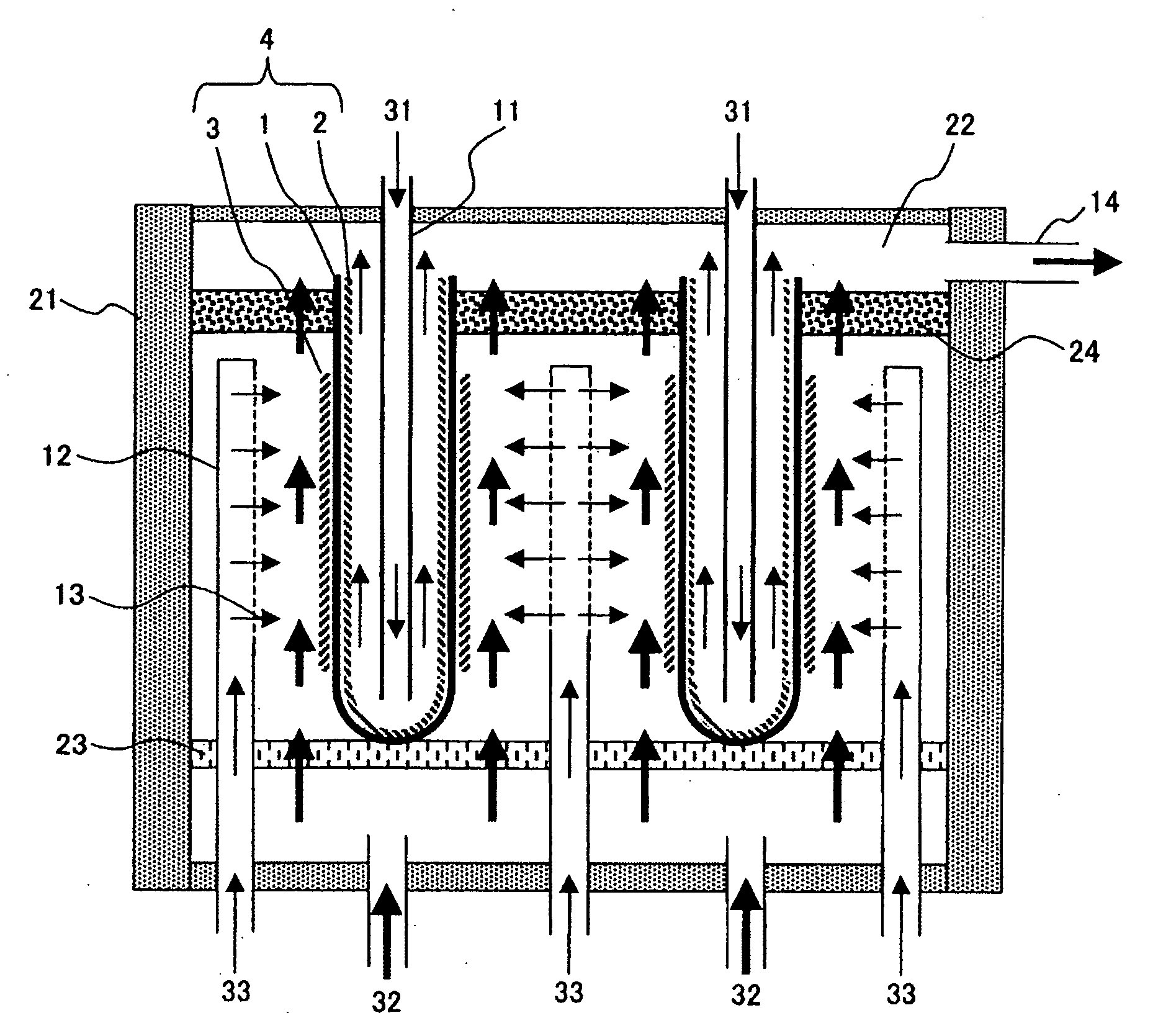
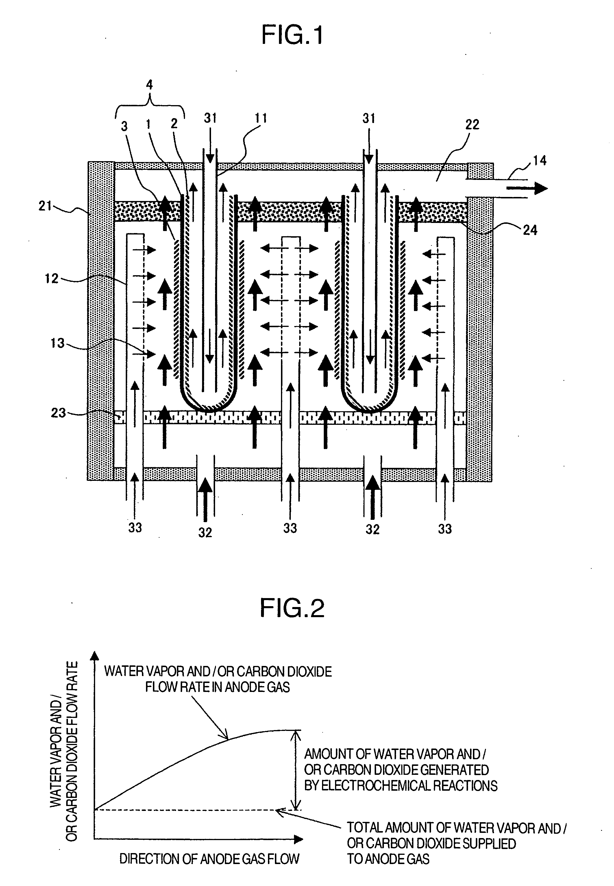
[0023]A schematic illustration of a power system comprising the bag tube type solid oxide fuel cells is given in FIG. 1. Each of the fuel cells 4 shown in FIG. 1 has a cathode 2 disposed on the inner surface of a bag tube type solid electrolyte 1 and an anode 3 disposed on its outer surface. The present invention can be applied equally where the cathode and the anode are changed in their positions. The fuel cells 4 are housed a module container 21. This module container 21 is designed to serve as a gas seal. The cathode gas, or air 31, is supplied to the bottom portion of each fuel cell 4 from an air inlet pipe 11, reverses its course at the bottom of the fuel cell 4 to flow back upwardly in the inside of the cell, inducing an electrochemical reaction in the cathode, and then passes into a space called combustion chamber 22.
[0024]A methane / water vapor mixed gas with an O / C ratio of 2 or higher, which functions as an anode gas, is supplied to the lower portion of each fuel cell throu...
example 2
[0028]A modification of Example 1 is shown in FIG. 5. Methane gas 44 in the fuel distribution pipes 12 may be heated to 500° C. or higher by heat transfer from the fuel cells 4, provoking a possibility of causing carbon deposition. When carbon deposition takes place in the fuel distributing pipes 12, the fuel distributing channels may be blocked, so that it needs to control the temperature of methane gas in the fuel distribution pipes to stay 500° C. or less.
[0029]In this embodiment of the invention, atomized water with an O / C ratio of lower than 2 is sprayed to methane gas 33 by an atomized water spray means 25 to control the rise of temperature of methane gas 33 by latent heat of evaporation of the atomized water.
[0030]In another modification, the fuel distribution pipes may be designed to have a dual structure, with methane gas 33 being flown in the inside passage while a cooling gas flown in the outside passage to thereby control the rise of temperature of methane gas 33.
example 3
[0031]A plan sectional view of a fuel cell power system comprising an assemblage of a plurality of fuel cells 4 is shown in FIG. 6 as another modification of Example 1. FIG. 7 is a side sectional view taken along the line A-A of FIG. 6.
[0032]Since one fuel cell can produce only a small voltage of about 1 V, usually a large number of cells are used by electrically connecting them in series by electrical connectors 27 to obtain a high output voltage. In case the fuel cells 4 electrically connected in series are disposed adjacent to each other, an insulator 26 is interposed between the adjoining cells since the anodes 3 on the outer surfaces of the respective fuel cells 4 differ from each other in electric potential. Insulators 26 are also used for securing insulation between the anodes and the module container 21, insulation between the electrical connectors 27 and the module container 21, and insulation between the electrical connectors 27 differing from each other in electric potent...
PUM
 Abstract
Description
Claims
Application Information
 - R&D
- Intellectual Property
- Life Sciences
- Materials
- Tech Scout
- Unparalleled Data Quality
- Higher Quality Content
- 60% Fewer Hallucinations
Browse by: Latest US Patents, China's latest patents, Technical Efficacy Thesaurus, Application Domain, Technology Topic, Popular Technical Reports.
© 2025 PatSnap. All rights reserved.Legal|Privacy policy|Modern Slavery Act Transparency Statement|Sitemap|About US| Contact US: help@patsnap.com


