Implantable catheter port

a catheter port and implanted technology, applied in the field of vascular access devices, can solve the problems of limiting the port's ability safety and overall useful life of the port, reducing the effectiveness of the port, so as to facilitate sealing, reduce volume, and increase flow

Inactive Publication Date: 2011-12-20
VECTOR CORP
View PDF18 Cites 7 Cited by
  • Summary
  • Abstract
  • Description
  • Claims
  • Application Information

AI Technical Summary

Benefits of technology

[0077]As noted above, ports of the prior art cannot be cleaned or cleared by wires following use. Thus an advantage of the present invention is that the smoothing of the internal features of the port enables cleaning or clearing with a wire. Additionally, the internal features of the port provides access for additional devices and / or allows additional medical procedures. For example, the port shape allows access to a cytology brush for performing cell sampling with in the internal port structure. In another aspect, electrodes may be passed through the port providing access to the vasculature or heart to determine electrophysiological characteristics. In yet another aspect, the port design allows for passage of additional catheters through the port body.
[0078]The septum 18 is shaped so that flow between the needle 20 and the reservoir 16 is increased over that of ports of the prior art. Additionally the septum 18 may be shaped so that regions of low flow within the port 10 where coagulation may occur is reduced relative to ports of the prior art. FIGS. 10 and 11 show two embodiments of the septum 18 of the present invention.
[0079]One method by which increased flow is accomplished is shown in FIG. 10. The reservoir side 40 of the septum 18 is concave so that it smoothly completes the upper surface of the reservoir 16 and generally mirrors the bottom 42 of the reservoir 16, resulting in an oval cross-sectional shape.
[0080]In the septum 18 of FIG. 11, the reservoir side 44 is also concave to complete the upper surface of the reservoir 16. It also has a dimple 52 that generally mirrors the bottom 46 of the reservoir 16, resulting in a cross-sectional shape that will minimize the volume in the central region of the reservoir 16 where blood flow is reduced and coagulation may occur. Additionally, the septum facilitates sealing.
[0081]The area of the port body 14 surrounding the septum 18 is designed so that the location of the septum 18 is tactilely identifiable through the skin. This is achieved in one embodiment by raising the edge 50 of the port body 14 surrounding the septum 18 above the level of the septum 18, as can be seen in FIGS. 4 and 10. The edge 50 may be rounded with a radius that is small enough so it can be easily sensed through the skin. However, the radius needs to be large enough so that it fits comfortably and will not work its way through the skin over time.
[0082]Optionally, as shown in FIG. 7, the port 10 has one or more suture holes 58. The suture holes 58 are optionally filed with silicone so that if a hole 58 is not pierced by a suture needle, it remains filled. In other aspects, a suture flange may be affixed or constructed into the port device. For example, the flange may be arranged circumferentially arranged such that, in a single port design, the flange may be arranged from one side of the distal tip of the outlet longitudinally around the port to the other side of the distal tip of the outlet. Alternatively, in a dual port device, the flange may be arranged from one side of the distal tip of the outlet longitudinally around the port to the other side of the mirrored distal tip of the outlet. In yet another embodiment, multiple shorter flanges may be arranged on the port body at specific points. The suture flange may be constructed of any suitable material, such as a biocompatible polyurethane or silicone.

Problems solved by technology

The buildup of blood or fluid is known as sludge, and limits the ability of the port to provide fluid flow in and out of the port, reducing the effectiveness, safety and overall useful life of the port.
If the port is used to transfuse blood, blood trapped in these dead spaces has the tendency to form clots and block the flow of fluid through the reservoir.
An additional limitation of existing designs is that the edges and corners of current designs also prevent the passage of wires through the port to clear a blockage.

Method used


Image

  • Implantable catheter port
  • Implantable catheter port
  • Implantable catheter port

Examples


example 1

Flow Visualization of Port Designs

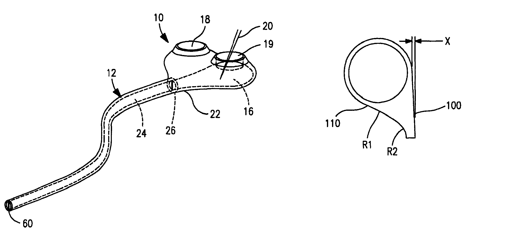
[0092]This example illustrates the superior flow rate characteristics of the tapered and tangential port design of the present invention. A Flow Visualization Experiment (FVE) was conducted showing the benefits of a tangent and tapered outlet port design versus both a tangent but not tapered outlet port design and a centered outlet port design typically used in the art.

[0093]The following port configurations were utilized to conduct the FVE. A tangent and tapered (TT) port design was constructed having a chamber volume of 0.742 ml and having a hydraulic diameter of the outlet (4 times the area of the outlet divided by the perimeter of the outlet) of 2.073 mm. The tangent and tapered design is shown in FIG. 19 wherein R1 is approximately 0.85 inches and R2 is approximately 0.4 inches.

[0094]A tapered not tangent (TNT) port design was constructed having a chamber volume of 0.847 ml and having a hydraulic diameter of the outlet (4 times the area of the ...


PUM


Abstract

A single or multi-port vascular access device including one or more reservoirs each covered by a needle-penetrable, self-sealing septum. The one or more reservoirs each open to an outlet in a stem to which the catheter is attached. The reservoir may be generally circular or ellipsoid in shape and large enough so that fluid movement into and out of the needle is unimpeded. In order to maximize flow between the reservoir and catheter and to minimize any regions of impeded or low fluid flow where coagulation or cell shearing may occur, the fluid passage leading from the reservoir through the outlet into the catheter is defined by unique tapered and tangential geometries. For example, the outlet surface may be globally tangent along the entire reservoir surface, or may be globally tangent along only one side of the reservoir surface.

Description

CROSS REFERENCE TO RELATED APPLICATION(S)[0001]This application claims the benefit of priority under 35 U.S.C. §119(e) of U.S. Ser. No. 60 / 942,722, filed Jun. 8, 2007, the entire content of which is incorporated herein by reference.BACKGROUND OF THE INVENTION[0002]1. Field of the Invention[0003]The present invention relates generally to vascular access devices and more specifically to subcutaneously implanted catheter ports.[0004]2. Background Information[0005]A variety of implantable devices, known as subcutaneous ports, are utilized to administer therapies that require central venous access through a non-coring needle received by the port, obviating the need for transdermal central venous catheters. For applications such as bodily fluid exchange and / or removal therapies, drug delivery, pheresis, hemofiltration, hemodialysis and other applications that must be periodically repeated, subcutaneous ports are preferable to other methods of accessing a patient's vascular system, such as...

Claims


Application Information

Patent Timeline
Patent Type & Authority Patents(United States)
IPC IPC(8): A61M37/00
CPCA61M39/0208A61M2039/0211
Inventor POWLEY, NICHOLAS R.KVEEN, GRAIG LEONARDGEER, DONALDALLEX, STEVENZAWACKI, JOHN ARTHUR
Owner VECTOR CORP
Why Eureka
Try Eureka