Cooling structure for rotor core in electric rotating machine

a cooling structure and rotating machine technology, applied in the direction of cooling/ventilation arrangement, magnetic circuit rotating parts, shape/form/construction, etc., can solve the problems of increasing iron loss induced increasing iron loss induced near the surface of the iron core, and not negligible eddy current loss induced in the embedded permanent magnet in the rotor core. , to achieve the effect of suppressing the temperature increase thereof, avoiding the reduction of developed torque, and suppressing

Active Publication Date: 2011-12-20
KK TOSHIBA +1
View PDF14 Cites 31 Cited by
  • Summary
  • Abstract
  • Description
  • Claims
  • Application Information

AI Technical Summary

Benefits of technology

[0010]In the rotor for an electric rotating machine and the electric rotating machine of the invention, when the rotor is thus constructed and refrigerant is caused to flow from the hollow shaft of the rotating shaft, the rotor is cooled such that temperature increase thereof can be suppressed. Since the refrigerant flows through the d-axis through holes provided near the rotor core particularly in the construction, a surface layer of the rotor core and the permanent magnets can effectively be cooled. Accordingly, a reduction in the developed torque can be avoided since the temperature increase in the permanent magnets can be suppressed and the demagnetization can be prevented.

Problems solved by technology

However, an iron loss (the sum of hysteresis loss and eddy current loss) induced in a rotor core is increased and particularly an iron loss induced near a surface of the iron core is increased when the rotational speed is increased.
Furthermore, an eddy current loss induced in a permanent magnet embedded in a rotor core is not negligible, either.
In the structure, however, the cooling performance is low since cooling by air is employed.

Method used


Image

  • Cooling structure for rotor core in electric rotating machine
  • Cooling structure for rotor core in electric rotating machine
  • Cooling structure for rotor core in electric rotating machine

Examples


first embodiment

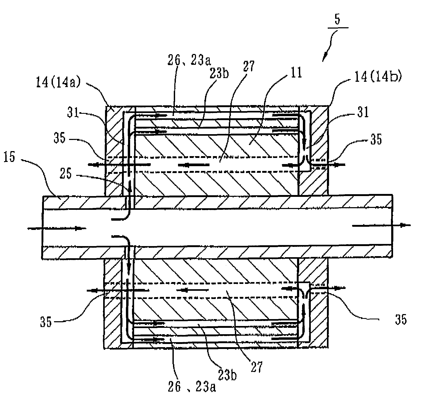
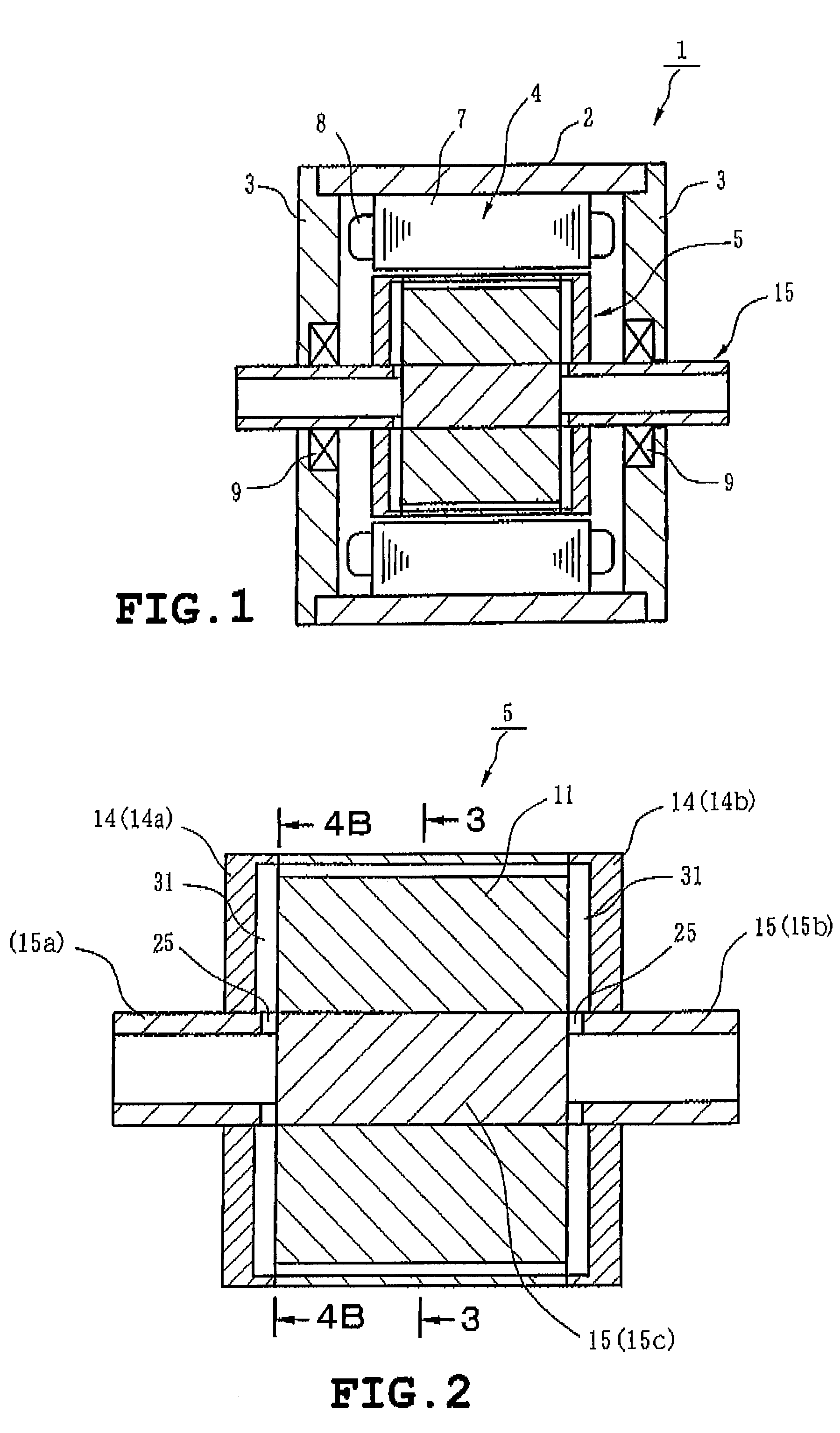
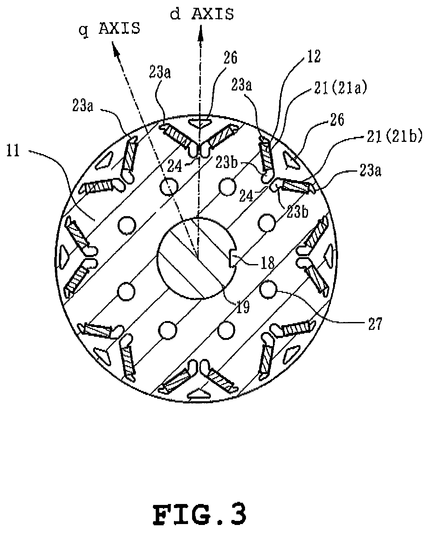
[0052]FIG. 2 is a longitudinal side section of the electric rotating machine including a d-axis of the rotor 5 of a The rotor 5 comprises a rotor core 11, permanent magnets 12 (see FIG. 3) embedded in the rotor core 11, two presser plates 14a and 14b pressing both end faces of the rotor core 11 respectively, and a rotating shaft 15. FIG. 3 is a sectional view of the rotor 5 taken along line 3-3 in FIG. 2. The rotor core 11 is formed by punching out a magnetic material into a planar shape as shown in FIG. 3, whereby a core piece is obtained. A plurality of the core pieces is stacked and axially crimped. The rotating shaft 15 is rotatably fitted in a hole 19 having a central key 18 of the rotor core 11.

[0053]The rotor 5 of the embodiment is a permanent magnet embedded type. A plurality of magnet insertion holes 21 through which the permanent magnets 12 are embedded is provided in a circumference of the rotor core 11. FIG. 3 shows the case where the number of poles is 8. Magnet insert...

second embodiment

[0069]In the second embodiment, when poured into the left hollow shaft portion 15a, the refrigerant flows into the voids 23b axially running through the rotor core 11 in contact with the permanent magnets 12. Accordingly, the permanent magnets 12 are cooled further effectively. Consequently, since the temperature increase of the permanent magnets is suppressed, the permanent magnets are prevented from demagnetization, whereupon reduction in the developed torque can be avoided.

[0070]A third embodiment of the invention will be described with reference to FIGS. 8, 9A and 9B. In these figures, identical or similar parts are labeled by the same reference symbols as those in FIGS. 2 to 5 of the first embodiment. FIG. 8 is a longitudinal section of the rotor 5 of the embodiment. FIGS. 9A and 9B illustrate an outer configuration of the left presser plate 14a pressing the rotor core 11 together with a sectional configuration of the rotating shaft 15 extending through the left presser plate 1...

third embodiment

[0074]In the third embodiment, when poured into the left hollow shaft portion 15a, the refrigerant flows through the three types of through-holes, that is, the d-axis through-holes 26, voids 23a, voids 23b in the rotor core 11. Accordingly, since the permanent magnets 12 and the rotor core 11 are cooled further effectively, reduction in the developed torque can be avoided.

[0075]A fourth embodiment of the invention will be described with reference to FIGS. 10, 11A and 11B. In these figures, identical or similar parts are labeled by the same reference symbols as those in FIGS. 8, 9A and 9B of the third embodiment. FIG. 10 is a longitudinal section of the rotor 5 of the embodiment. FIGS. 11A and 11B illustrate an outer configuration of the left presser plate 14a pressing the rotor core 11 together with a sectional configuration of the rotating shaft 15 extending through the left presser plate 14a. FIG. 11B is a view of a joint surface of the left presser plate 14a and the rotor core 11...


PUM


Abstract

A rotor for an electric rotating machine includes d-axis through holes located on respective d-axes, hollow shafts formed in both axial sides of a rotating shaft not inserted into a rotor core, presser plates mounted on both axial ends of the rotor core, cooling grooves formed in faces of the presser plates in contact with the rotor core, a plurality of presser plate refrigerant outlet holes in the presser plates, the presser plate refrigerant outlet holes of one of the presser plates having diameters different from diameters of the presser plate refrigerant outlet holes of one of the other presser plates, and a refrigerant channel formed so that a refrigerant supplied into one of the hollow shafts of the rotating shaft flows through the refrigerant channel and further through the hollow shaft wall hole of said one hollow shaft and the radial grooves of the respective presser plates.

Description

TECHNICAL FIELD[0001]The present invention relates to an electric rotating machine using a permanent magnet, and more particularly to a rotor for such an electric rotating machine in which the permanent magnet and a rotor core can be cooled by a refrigerant, and the electric rotating machine provided with the rotor.BACKGROUND ART[0002]Recent electric rotating machines have been reduced in size by employment of a structure of embedding a permanent magnet in a rotor, a technique of utilizing reluctance torque by giving a magnetically salient polarity to a rotor as well as magnetic torque, and the like. One of present problems to be overcome is considered to increase a rotational speed of a rotor.[0003]However, an iron loss (the sum of hysteresis loss and eddy current loss) induced in a rotor core is increased and particularly an iron loss induced near a surface of the iron core is increased when the rotational speed is increased. Furthermore, an eddy current loss induced in a permanen...

Claims


Application Information

Patent Timeline
Patent Type & Authority Patents(United States)
IPC IPC(8): H02K9/19H02K5/20H02K9/00H02K9/197H02K5/04
CPCH02K1/2766H02K1/32H02K9/19H02K9/197
Inventor MATSUBARA, MASAKATSUHIRANO, YASUOHANAI, TAKASHIMOCHIZUKI, MOTOYASU
Owner KK TOSHIBA
Why Eureka
Try Eureka