Micro-structure fabrication method

a micro-structure and fabrication method technology, applied in the direction of manufacturing tools, magnetic bodies, instruments, etc., can solve the problems of work piece deformation, work piece buckles or damage, work piece deformation, etc., to reduce the possibility of deformation, buckling, and the efficiency of deformation of work pieces

Inactive Publication Date: 2011-12-27
CANON KK
View PDF8 Cites 4 Cited by
  • Summary
  • Abstract
  • Description
  • Claims
  • Application Information

AI Technical Summary

Benefits of technology

[0023]The present invention provides a structure fabrication method for fabricating a structure capable of efficiently deforming a work piece plastically in a desired shape by plastically deforming part of the structure during the fabrication of the structure including an inclined part inclined to the principal plane of a substrate.
[0026]According to the present invention, in an external force applied to a work piece, in comparison with related art, while a component force of the external force that is not contributing to the deformation of the work piece decreases, a component force that is contributing to the deformation of the work piece increases, so that the efficiency of deforming the work piece can be improved.
[0027]Also, at a desired position of the work piece, the plastic deformation can be facilitated as well as at positions other than that, and the possibility of deformation, buckling, and failure of the work piece can be reduced.

Problems solved by technology

Depending on the material, size, and structure of a work piece, the work piece may fall short of the mechanical strength.
When such a work piece with insufficient mechanical strength is deformed, unless the force is efficiently transmitted to the work piece, the work piece may buckle or damage during the deforming.

Method used


Image

  • Micro-structure fabrication method
  • Micro-structure fabrication method
  • Micro-structure fabrication method

Examples


embodiments

[0099]With the following embodiments, the present invention will be described further in detail; however, the invention is never limited to these.

first embodiment

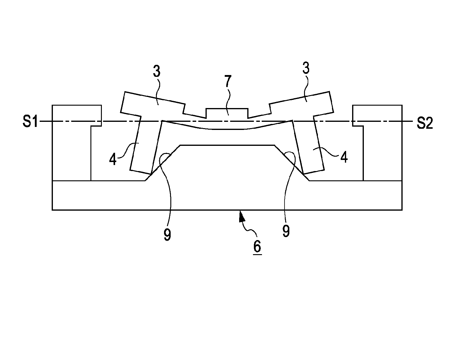
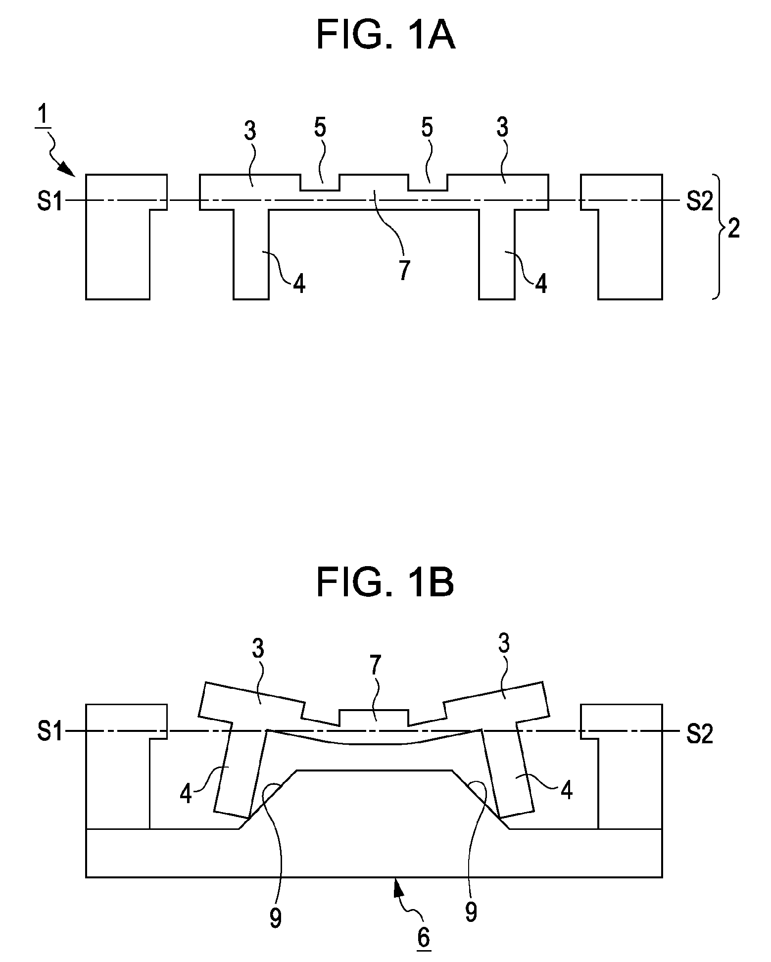
[0100]In this embodiment, a fabrication method of a structure including an inclined part inclined in one direction to the principal plane (including a planar plane parallel to the principal plane) of the substrate in an out-of-plane state will be described.

[0101]FIGS. 7A to 7L show processes of a structure fabricating method according to the embodiment. Reference characters (a) to (i) in FIGS. 7A to 7L correspond to the processes (a) to (i), respectively.

[0102]First, according to the processes (a) to (g), work pieces 101 and 102 and projections 103 and 104 of the work pieces are formed.

[0103](a): Mask layers 115 are formed on the surface of a semiconductor layer 112 of a substrate 111.

[0104]The substrate 111 has a laminated structure having an insulating layer 113 sandwiched between two layers, and these layers are called in this specification as the semiconductor layer, the insulating layer, and a supporting layer from the top in that order. The substrate 111 may use a SOI (silicon...

second embodiment

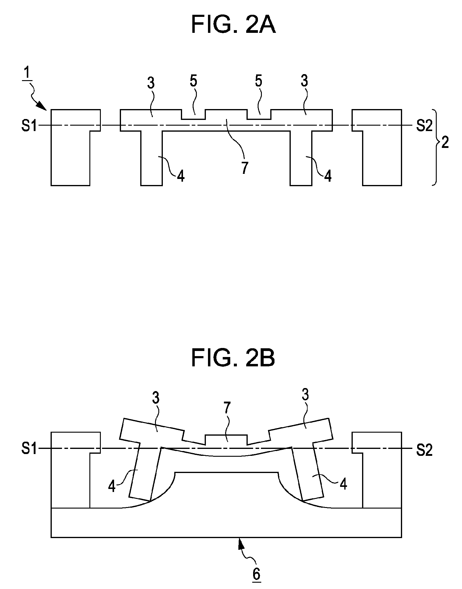
[0140]By changing part of the processes of the first embodiment, a plurality of work pieces can be fabricated with different folding angles. In a second embodiment, three methods will be described. According to the embodiment, the folding work toward one direction relative to a plane parallel to the principal plane of the substrate will be described in the same way as in the first embodiment.

[0141]In a first method, the projections 103 and 104 of the work pieces are provided at positions different from each other in distance from the reference point for folding the work pieces 101 and 102.

[0142]Such projections 103 and 104 of the work pieces can be fabricated by changing the region for forming the mask layers 120 in the process (f) of the first embodiment as well as by changing the region for forming the through holes 121 in the process (g).

[0143]The situations when the block 134 is pressed onto the bottom surface of the supporting layer 114 and the projections 103 and 104 of the wo...


PUM

PropertyMeasurementUnit
widthaaaaaaaaaa
angleaaaaaaaaaa
temperatureaaaaaaaaaa

Abstract

A micro-structure fabrication method fabricates a micro-structure including an inclined part inclined to a principal plane of a substrate by plastically deforming a work piece having the substrate with the principal plane. The structure fabrication method includes the steps of providing in the work piece a projection configured to protrude from a first surface and away from the principal plane of the substrate, and bending the work piece toward a second surface opposite to the first surface. The bending is accomplished by applying a force on a block including an inclined pressure plane that is abutted on the projection for plastically deforming the work piece, in which in bending the work piece, the direction of a first force applied on the work piece intersects with the direction of a second force of the inclined pressure plane pushing the projection.

Description

BACKGROUND OF THE INVENTION[0001]1. Field of the Invention[0002]The present invention relates to a structure fabrication method for fabricating a structure including a beam structure typified by a comb-structure for use in sensors and actuators to be fabricated by an MEMS technique. “MEMS” is an abbreviation for “micro electro mechanical systems”.[0003]2. Description of the Related Art[0004]In a vertical comb-structure, also called a VC, a pair of comb fingers are arranged to mate with each other, and any one of the comb fingers is supported by an elastic body so as to be out-of-plane deformable.[0005]For fabricating such a structure, using a micro-fabrication technique applied in a semiconductor fabrication method and called the MEMS technique, a micro-structure with a width of one comb-finger of about 5 μm can be fabricated, for example.[0006]Applications of the vertical comb-structure fabricated by the MEMS technique include micromirrors for optical path changing and variable cap...

Claims


Application Information

Patent Timeline
Patent Type & Authority Patents(United States)
IPC IPC(8): B21D39/00B23P11/00
CPCB81C1/00174B81B2203/058Y10T29/49922Y10T29/49861Y10T29/4902Y10T29/49904
Inventor ZAITSU, YOSHITAKACHANG, CHIENLIUMAJIMA, MASAO
Owner CANON KK
Why Eureka
Try Eureka