Flexible pipe with a permeable outer sheath and a method of its manufacturing

a flexible pipe and outer sheath technology, applied in the field of flexible pipes, can solve the problems of critical compressive forces in the armouring layer, damage to the outer sheath, and large machine requirements compared to those of the rope and cable industry, and achieve the effects of improving the flexibility of the pipe, preventing damage, and being flexible and yet fixed structur

Active Publication Date: 2011-12-27
NAT OILWELL VARCO DENMARK
View PDF33 Cites 13 Cited by
  • Summary
  • Abstract
  • Description
  • Claims
  • Application Information

AI Technical Summary

Benefits of technology

[0030]It is an advantage of the invention that a relatively flexible, yet fixed structure of the outer sheath is provided. This is e.g. achieved in that the outer sheath is held together in an array of discrete spots or along linear or curved paths.
[0031]The flexibility is maintained because the stiffness in shear in the wires of adjacent protective layers may be made much larger (e.g. 5 to 10 times larger) in the areas being locally held together than outside these areas. This allows a change of angles between the wires of two adjacent layers of the outer protective sheath during elongation or shortening of the pipe.
[0032]In an embodiment of the invention, the armouring layers are NOT chemically bonded to the inner liner or to possible intermediate layers or membranes but is able to move relative to this or these layers, thereby improving the flexibility of the pipe. This type of pipe is normally termed an “un-bonded” pipe.
[0033]In an embodiment of the invention a water-permeable membrane is placed between the outermost armour layer and the outer sheath, thereby providing protection of the armouring layers during manufacturing, prior to the application of the outer sheath, and also providing a barrier for ingress of fine particles (e.g. sand) from the surrounding environment to the armour layers.
[0034]In an embodiment of the invention, a flexible pipe is provided, the flexible pipe comprising an inner liner creating a barrier against leakage of fluid being transported by the pipe, the liner being surrounded by one or more armouring layers, the armouring layers comprising one or more armouring profiles, the armouring layers being surrounded by a thin permeable membrane, the membrane being surrounded by an outer protective sheath which comprises at least two layers wound from one or more wires, the at least two layers being wound with opposite winding angles, the wires comprising chords which are partially (i.e. locally) held together and the wound layers are partially (i.e. locally) held together.
[0035]A further advantage of the invention is that the concentration of harmful materials diffusing out through the liner from the interior of the pipe may be held at a level lower than the maximum allowable value for the armouring layer or layers. This is achieved in that the harmful materials are dissolved into the seawater surrounding the armour and subsequently removed from the pipe layers by diffusion due to the difference in concentration relative to the ambient surrounding sea. Further, if the pipe is used in a marine environment for the transport of fluids at elevated temperatures, the surrounding water aids at ensuring an effective cooling of the armouring layer(s) thereby preventing its damage due to overheating from the fluid transported by the pipe. Also, the armouring layer is protected by the outer protective sheath against seizing, fouling, wear, impact loads and critically large compressive forces.

Problems solved by technology

A problem with this type of pipe is that the armouring layer—because of the tight sheath around it—has to be able to withstand the chemical activity from fluids escaping from the interior of the pipe, e.g. by diffusion and thereby accumulates around the armouring layers.
A problem with both types of pipes is that the outer sheath—permeable or not—may hinder a radial expansion of the wound armouring layers which may result in the creation of critically large compressive forces in the armouring layer when the pipe is subject to an outer hydrostatic pressure.
These compressive forces may lead to bursting of the outer sheath or to instability of the armouring profiles resulting in damaging deformations.
A problem with the braiding of an outer sheath for a flexible pipe is that the circumferences of typical flexible pipes are much larger than those of even large ropes (e.g. for anchors) and cables, and which therefore require very large machines compared to those of the rope and cable industry.
Further, the velocity of the braiding process is considerably lower than what is typical for winding processes in connection with the manufacture of flexible pipes and therefore not easily integrated in a normal manufacturing flow.

Method used


Image

  • Flexible pipe with a permeable outer sheath and a method of its manufacturing
  • Flexible pipe with a permeable outer sheath and a method of its manufacturing
  • Flexible pipe with a permeable outer sheath and a method of its manufacturing

Examples


Embodiment Construction

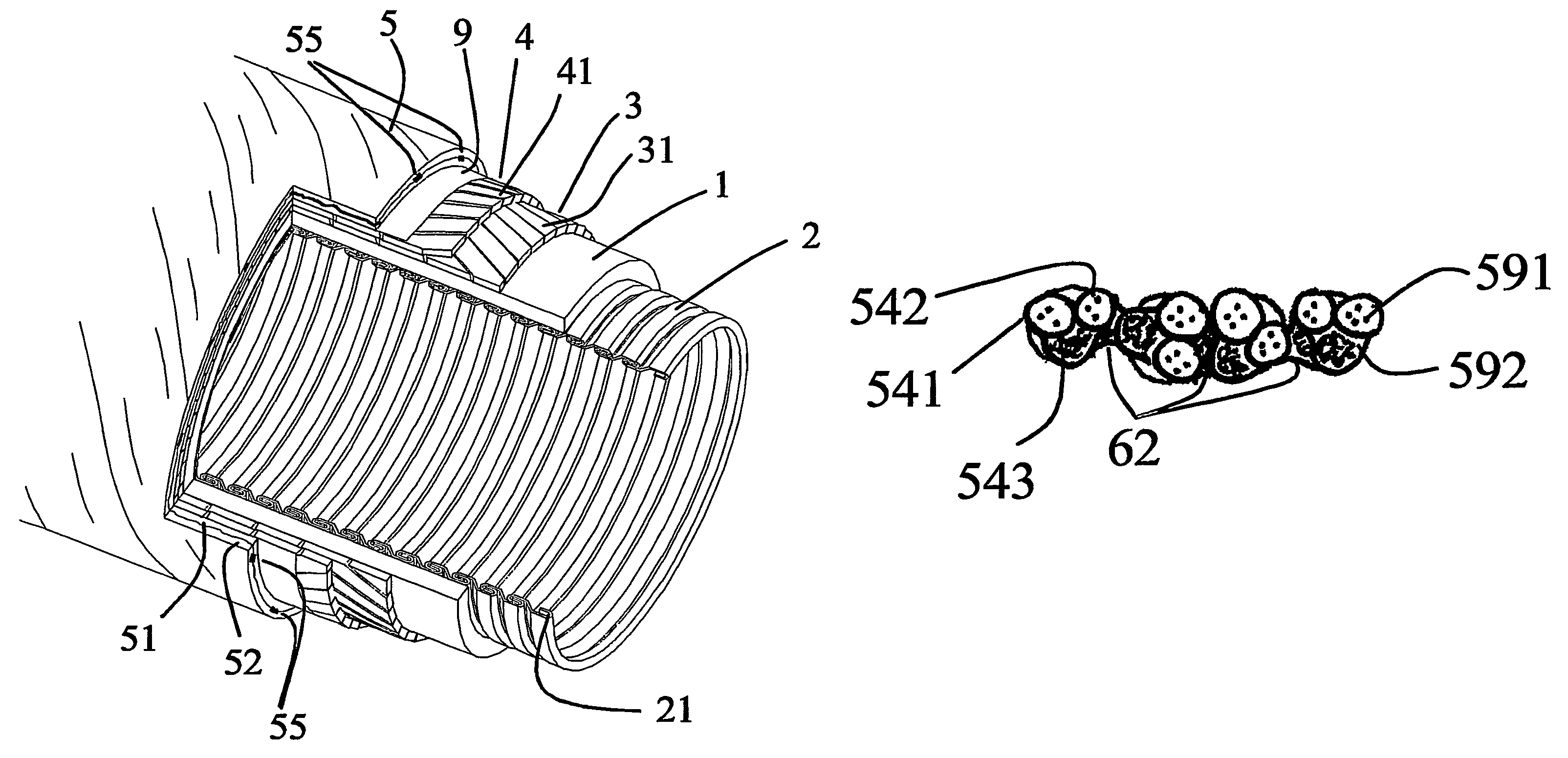
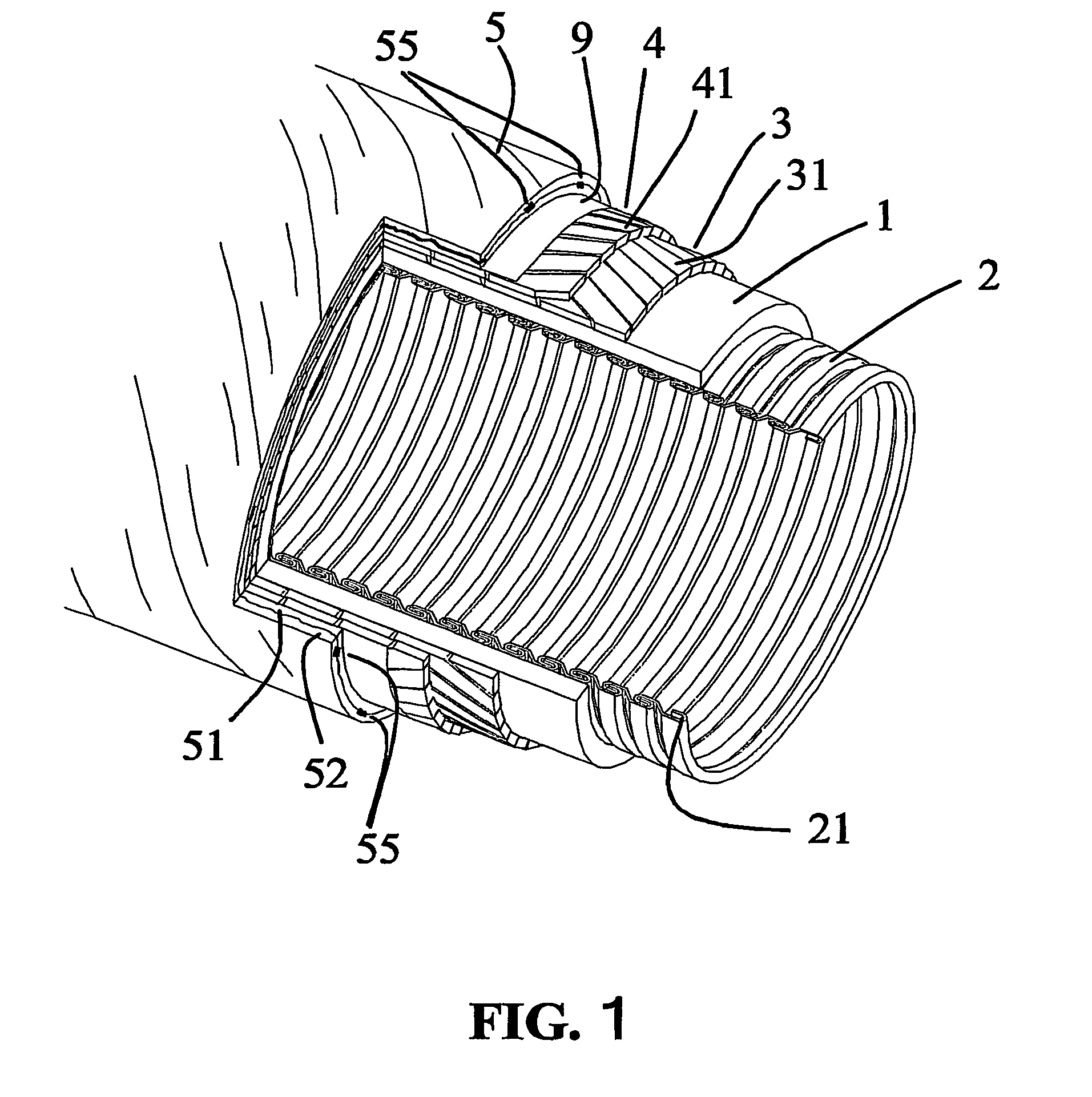
[0085]FIG. 1 shows a perspective view with a cut-out of an embodiment of a flexible pipe according to the invention illustrating various layers of the pipe.

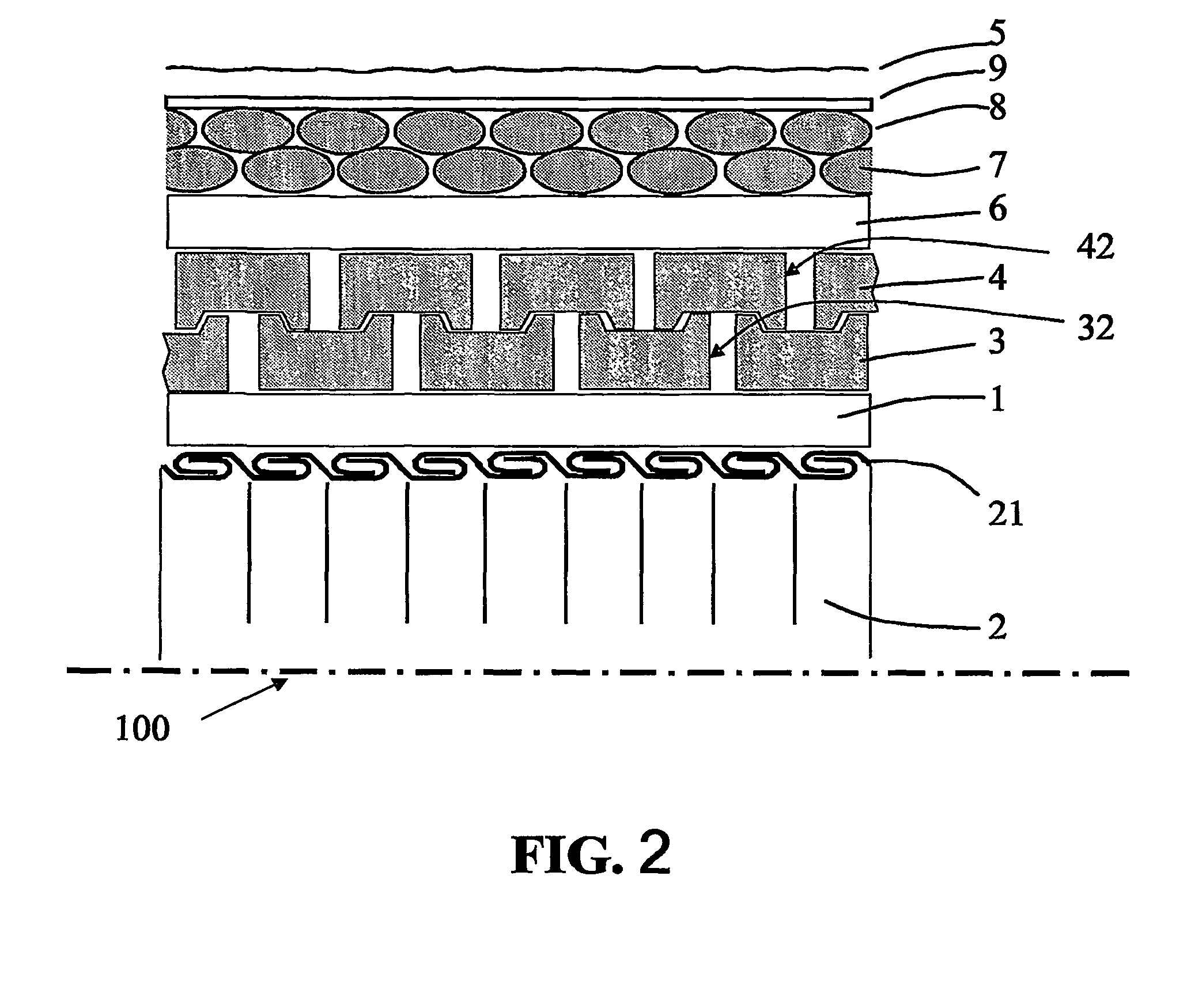
[0086]In FIG. 1, an inner barrier liner 1 is shown surrounding an (optional) inner armouring layer 2. The purpose of the inner armouring layer is to prevent a collapse of the inner liner in case the pressure difference between its inner and outer surface exceeds the value which the liner itself is able to withstand. The inner armouring layer 2 comprises a metal tape 21 that is helically wound to create an inner tube. The metal tape is—during the winding process—provided with flaps that are intertwined thereby locking individual turns of the tape to each other in such a way that the inner armouring layer 2 is capable of being deflected out of its longitudinal direction. While the inner armouring layer is not inherently tight, the surrounding inner liner 1 has the purpose of fully or partially preventing the escape of liquid or gas...


PUM

PropertyMeasurementUnit
water flow velocity indexaaaaaaaaaa

Abstract

A flexible pipe for transporting a fluid in a marine environment. The pipe comprises a liner for confining the fluid, an armoring layer surrounding the liner, and an outer protective sheath surrounding the armoring layer and allowing radial expansion and contraction of the armoring layers. The outer protective sheath comprises at least two protective layers of helically wound composite wires with essentially opposite winding angles and locally held together, providing a relatively flexible yet fixed structure of the outer sheath. The outer sheath is held together in an array of discrete spots or along linear or curved paths. Flexibility is maintained because the stiffness in shear in the wires of adjacent protective layers may be made much larger in areas being locally held together than outside these areas. This allows a change of angles between the wires of two adjacent layers of the outer protective sheath during elongation or shortening of the pipe.

Description

TECHNICAL FIELD[0001]The invention relates to a flexible pipe for transporting a fluid in a marine environment, the pipe comprising a) a liner for confining the fluid to be transported by the pipe, b) an armouring layer surrounding the liner, c) an outer protective sheath surrounding the armouring layer.[0002]The invention furthermore relates to: A method of manufacturing a flexible pipe for transporting a fluid in a marine environment, the method comprising the steps of a) providing a liner for confining the fluid to be transported by the pipe, b) providing an armouring layer surrounding the liner, c) providing an outer protective sheath surrounding the armouring layer.[0003]The invention may e.g. be useful in applications such as transport of pressurized liquids and gases (e.g. hydrocarbons, water, etc.), e.g. at elevated temperatures, in marine environments (i.e. environments comprising water, e.g. salt or fresh).BACKGROUND ART[0004]Flexible pipes of the above type are e.g. used ...

Claims


Application Information

Patent Timeline
Patent Type & Authority Patents(United States)
IPC IPC(8): F16L11/00B29C53/58F16L11/08
CPCB29C53/582F16L11/081F16L11/088F16L11/16
Inventor RYTTER, JAN
Owner NAT OILWELL VARCO DENMARK
Why Eureka
Try Eureka