Dual lane control of a permanent magnet brushless motor using non-trapezoidal commutation control

a permanent magnet, non-trapezoidal technology, applied in the direction of electronic commutators, motor/generator/converter stoppers, dynamo-electric converter control, etc., can solve the problem of not being well-suited to non-trapezoidal commutation schemes

Inactive Publication Date: 2011-12-27
HONEYWELL INT INC
View PDF29 Cites 18 Cited by
  • Summary
  • Abstract
  • Description
  • Claims
  • Application Information

AI Technical Summary

Problems solved by technology

However, it is not at all well-suited for non-trapezoidal commutation schemes, such as field oriented control (FOC) / space vector modulation (SVM) or sinusoidal commutation control.

Method used


Image

  • Dual lane control of a permanent magnet brushless motor using non-trapezoidal commutation control
  • Dual lane control of a permanent magnet brushless motor using non-trapezoidal commutation control
  • Dual lane control of a permanent magnet brushless motor using non-trapezoidal commutation control

Examples


Embodiment Construction

[0015]The following detailed description is merely exemplary in nature and is not intended to limit the invention or the application and uses of the invention. Furthermore, there is no intention to be bound by any theory presented in the preceding background or the following detailed description.

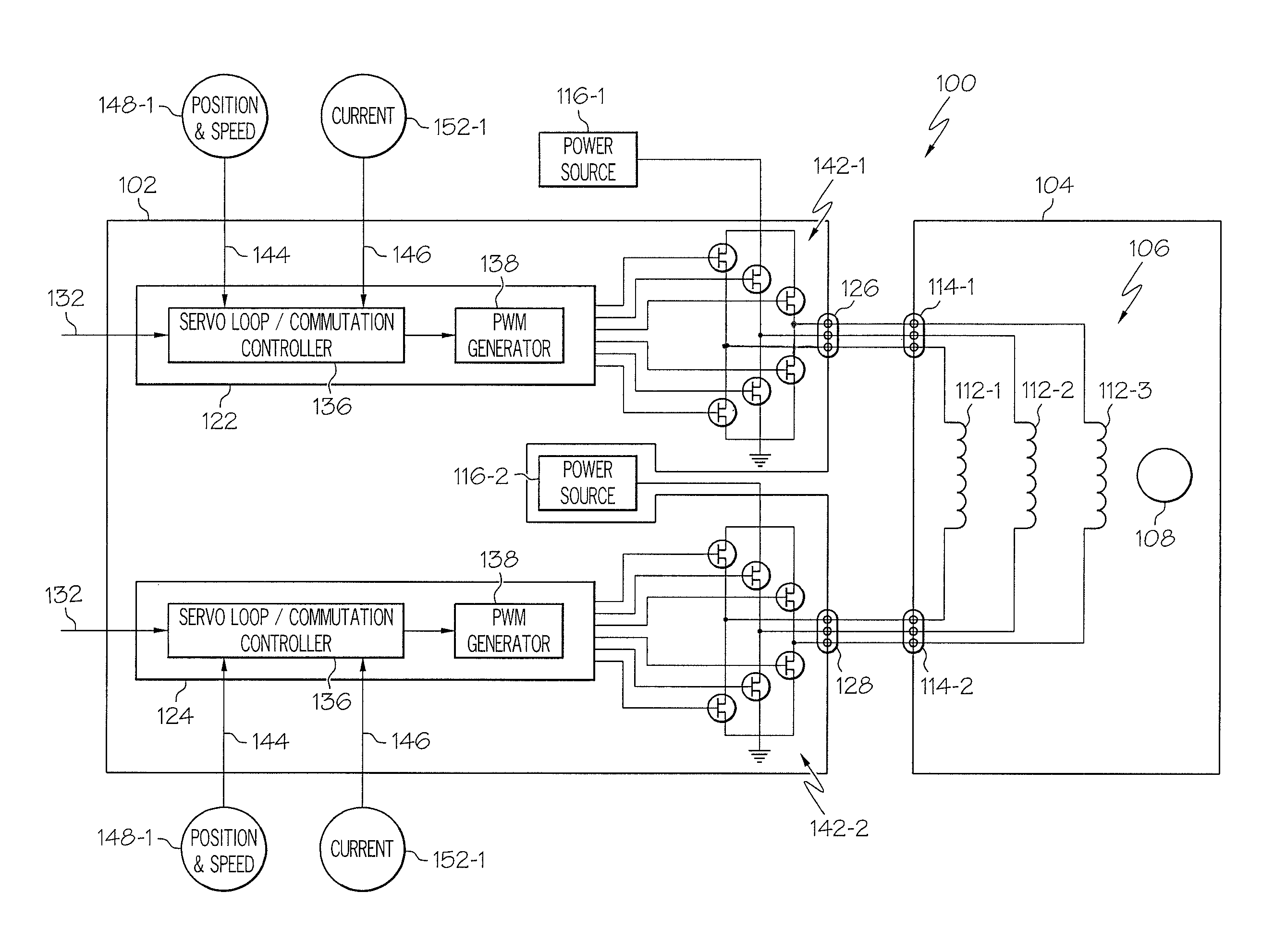
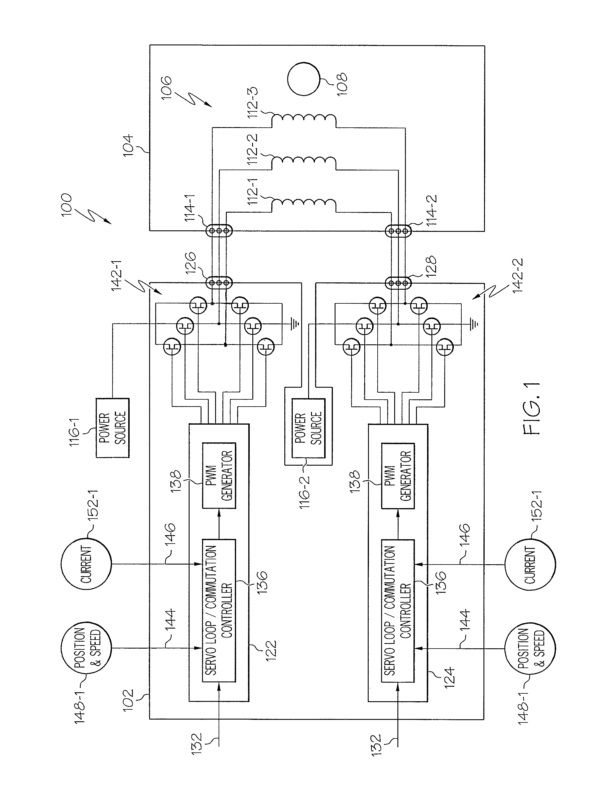
[0016]Referring first to FIG. 1, a functional block diagram of an exemplary dual lane motor control system is depicted. The motor control system 100 includes a motor control 102 and a motor 104. The motor 104 is preferably a multi-phase brushless machine, and most preferably a three-phase brushless machine, and includes a multi-phase stator 106 and a rotor 108. The stator 106 is implemented with a plurality of individual, electrically isolated stator windings, one each associated with each phase. Thus, in the depicted embodiment the stator includes three individual, electrically isolated stator windings 112 (e.g., 112-1, 112-2, 112-3). Each stator winding 112 includes two terminals 114, a fi...


PUM


Abstract

A motor control system and method implements non-trapezoidal motor control and meets established “fail passive” regulatory guidelines. In particular, a system and method of controlling a multi-phase brushless motor that includes a multi-pole permanent magnet rotor, and an individual, electrically isolated stator winding associated with each phase that includes a first terminal and a second terminal. A motor command is supplied to a motor control. The motor control is configured such that the first terminal of each stator winding is selectively coupled to a power source at a first duty cycle, and the second terminal of each stator winding is selectively coupled to a power source asynchronously with the first terminal of each stator winding at a second duty cycle.

Description

TECHNICAL FIELD[0001]The present invention generally relates to brushless motor control and, more particularly, to system and method for controlling a permanent magnet brushless motor using non-trapezoidal commutation control.BACKGROUND[0002]Aircraft are increasingly including electric motors to drive various system components, rather than presently or previously used pneumatic or hydraulic motors or other devices. For many aircraft systems, regulatory agencies have established guidelines for system design to accommodate postulated, yet highly unlikely events, such as a component within the system becoming unavailable or otherwise inoperable. In many instances, the established guidelines require that a system be designed to “fail passive” in the face of such postulated, yet highly unlikely events.[0003]In order to increase reliability and fault tolerance, and to meet the established regulatory guidelines, many electric motor control systems include redundant motor controls. One such...

Claims


Application Information

Patent Timeline
Patent Type & Authority Patents(United States)
IPC IPC(8): H02P1/04
CPCH02P6/14H02P27/08H02P2209/07
Inventor STRONG, RONALD E.WILKENS, DEAN R.
Owner HONEYWELL INT INC
Why Eureka
Try Eureka