Motor control device and compressor

a technology of motor control device and compressor, which is applied in the direction of electric generator control, dynamo-electric converter control, dynamo-electric gear control, etc., can solve the problems of periodic variations in the rotation speed of the compressor, the influence of the change in refrigerant gas pressure during the cycle of suction, compression and discharge, and the influence of load torqu

Active Publication Date: 2011-12-27
III HLDG 12 LLC
View PDF10 Cites 12 Cited by
  • Summary
  • Abstract
  • Description
  • Claims
  • Application Information

AI Technical Summary

Benefits of technology

[0003]The present invention relates to motor control devices that control a motor and to compressors.

Problems solved by technology

In a hermetic type compressor used in an air conditioner, a change in refrigerant gas pressure during cycles of suction, compression, and discharge is known to affect a load torque.
It is also known that the load torque associated with the refrigerant gas pressure varies in synchronism with the rotation of the compressor, resulting in periodic variations in rotation speed of the compressor.
Such periodic variations in rotation speed of the compressor produce vibration in the compressor itself, and also cause noise.

Method used


Image

  • Motor control device and compressor
  • Motor control device and compressor
  • Motor control device and compressor

Examples


example 1

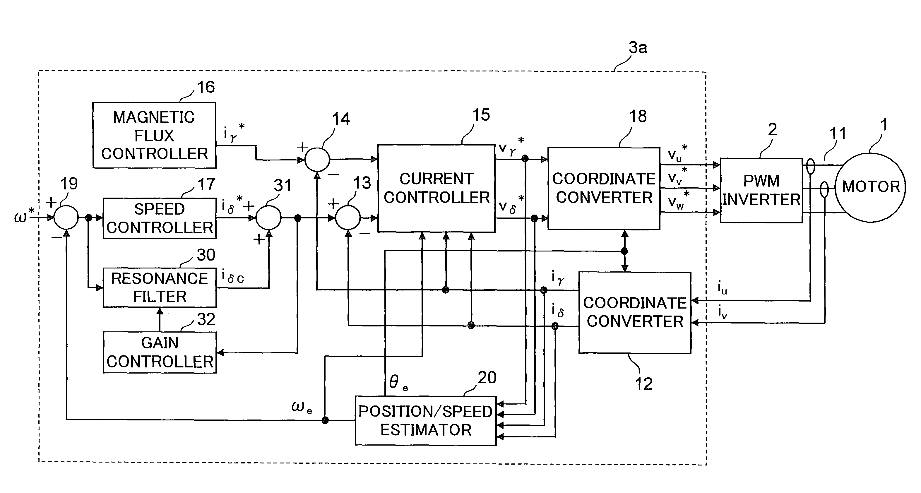
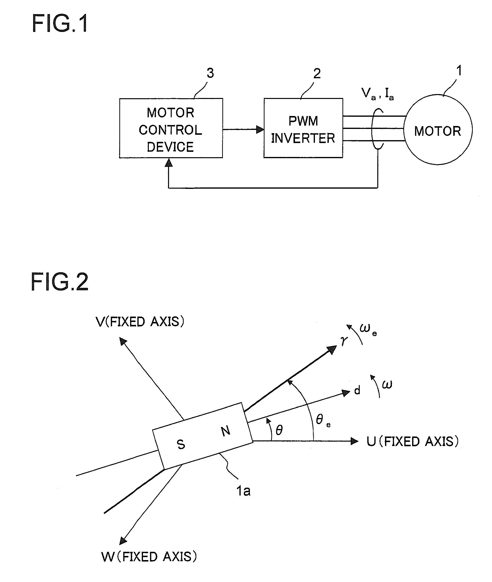
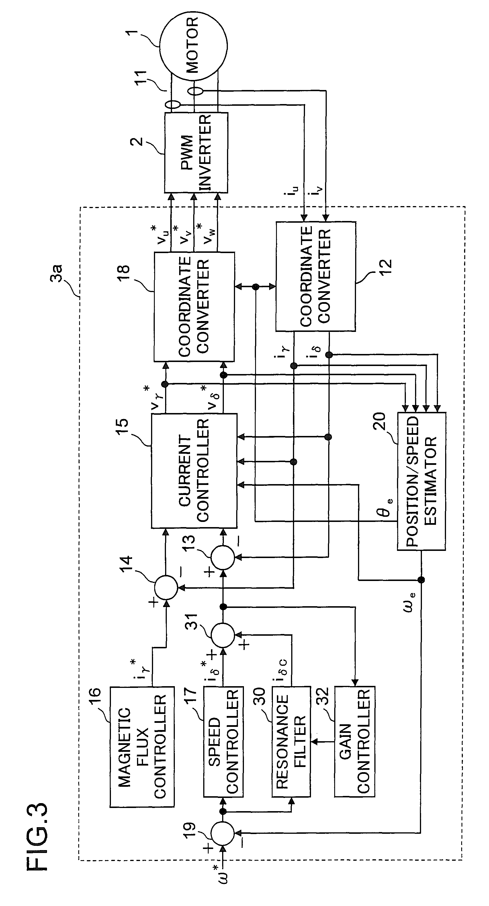
[0051]First, Example 1 of the invention will be described. FIG. 3 is a detailed block diagram of a motor drive system according to Example 1. The motor drive system shown in FIG. 3 includes the motor 1 and the inverter 2 shown in FIG. 1, a motor control device 3a serving as the motor control device 3 shown in FIG. 1, and a phase-current sensor 11. The motor control device 3a includes different parts designated with reference numerals 12 to 20 and 30 to 32. The motor control device 3a can be considered to include the phase-current sensor 11. The different parts constituting the motor control device 3 a can freely use all the values produced within the motor control device 3a.

[0052]The different parts constituting the motor drive systems of this example and other examples, which will be described later, update, at intervals of a predetermined period, the specified values (including iγ*, iδ*, vγ*, vδ*, vu*, vv*, and vw*), the state quantities (including iu, iv, iγ, iδ, θe, and ωe), or...

example 2

[0098]Next, Example 2 of the invention will be described. FIG. 11 is a detailed block diagram of a motor drive system according to Example 2. The motor drive system shown in FIG. 11 includes the motor 1 and the inverter 2, which are shown in FIG. 1, a motor control device 3b serving as the motor control device 3 shown in FIG. 1, and the phase-current sensor 11. The motor control device 3b includes different parts designated with reference numerals 12 to 20 and 30 to 32. The motor control device 3b can be considered to include the phase-current sensor 11. The different parts constituting the motor control device 3b can freely use all the values produced within the motor control device 3b.

[0099]In the motor control device 3a shown in FIG. 3, the resonance filter 30 receives a speed deviation (ω*−ωe) as an input signal. However, in the motor control device 3b shown in FIG. 11, the resonance filter 30 receives, as an input signal, the specified δ-axis current value is from the speed co...

example 3

[0101]Next, Example 3 of the invention will be described. FIG. 12 is a detailed block diagram of a motor drive system according to Example 3. The motor drive system shown in FIG. 12 includes the motor 1 and the inverter 2, which are shown in FIG. 1, a motor control device 3c serving as the motor control device 3 shown in FIG. 1, and the phase-current sensor 11. The motor control device 3c includes different parts designated with reference numerals 12 to 20, 31, and 32, and a resonance filter 30c. The motor control device 3c can be considered to include the phase-current sensor 11. The different parts constituting the motor control device 3c can freely use all the values produced within the motor control device 3c.

[0102]In the motor control device 3a shown in FIG. 3, the resonance filter 30 calculates the corrected δ-axis current value iδC from the speed deviation (ω*−ωe). However, in the motor control device 3c shown in FIG. 12, the resonance filter 30c calculates the corrected δ-a...


PUM


Abstract

A motor control device performing vector control for a motor that drives a load whose load torque varies periodically. The motor control device has: a motor speed deriving portion estimating or detecting a motor speed; a speed controller producing a specified torque current value such that the motor speed is made to follow a specified motor speed value fed from outside; a resonance filter producing a corrected torque current value by receiving a control value that varies with variations in the load torque and emphasizing a periodic variation component of the control value; a torque current corrector producing a specified superimposed torque current value by superimposing the corrected torque current value on the specified torque current value; and an adjusting portion adjusting, based on the specified superimposed torque current value, a degree of emphasis placed on the variation component by the resonance filter. The vector control is performed according to the specified superimposed torque current value.

Description

[0001]This nonprovisional application claims priority under 35 U.S.C. §119(a) on Patent Application No. 2007-165059 filed in Japan on Jun. 22, 2007, the entire contents of which are hereby incorporated by reference.BACKGROUND OF THE INVENTION[0002]1. Field of the Invention[0003]The present invention relates to motor control devices that control a motor and to compressors.[0004]2. Description of Related Art[0005]A load factor of a motor often entails periodic load variations. A compressor used in an air conditioner or the like is an example of a product including such a load factor. In a hermetic type compressor used in an air conditioner, a change in refrigerant gas pressure during cycles of suction, compression, and discharge is known to affect a load torque. It is also known that the load torque associated with the refrigerant gas pressure varies in synchronism with the rotation of the compressor, resulting in periodic variations in rotation speed of the compressor. Such periodic ...

Claims


Application Information

Patent Timeline
Patent Type & Authority Patents(United States)
IPC IPC(8): H02P7/00H02P21/00H02P27/00H02P27/04H02P6/06H02P6/08H02P6/18H02P6/28
CPCH02P21/0003H02P21/0039H02P21/146F04B49/065F04B2203/0207F04B2203/0209F04C18/0215F04C28/08H02P21/18H02P21/24
Inventor HASHIMOTO, EIICHIRO
Owner III HLDG 12 LLC
Why Eureka
Try Eureka