Abnormality detecting device for storage element, abnormality detecting method for storage element, abnormality detecting program for storage element, and computer-readable recording medium storing abnormality detecting program

a technology of abnormality determination and storage elements, applied in secondary cells, electrochemical generators, instruments, etc., can solve the problems of shortening the life of the storage device as a whole, internal resistance to rise, and capacity reduction, so as to improve the accuracy of abnormality determination on the respective storage portions and upgrade the safety of the storage portions.

Inactive Publication Date: 2011-12-27
PANASONIC CORP
View PDF17 Cites 6 Cited by
  • Summary
  • Abstract
  • Description
  • Claims
  • Application Information

AI Technical Summary

Benefits of technology

[0023]An object of the invention is to provide an abnormality detecting device for a storage element that improves accuracy of abnormality detection on the storage element by performing an abnormality determination on the storage element without influences of a variance in capacity and the state of charge of the storage element.
[0025]In the abnormality detecting device for a storage element described above, an abnormality determination is performed on the respective storage portions using an amount of change of the voltages across the terminals of the respective storage portions caused by allowing the respective storage portions to stand after the states of charge of the respective storage portions are made equal. It thus becomes possible to perform a determination on the basis of an amount of change of the voltages across the terminals when the storage devices are allowed to stand after a variance in capacity and a variance of states of charge, such as a variance in voltage, of the respective storage devices are eliminated. Hence, because there will be no influences of a variance of the states of charge, accuracy of the abnormality determination on the respective storage portions can be improved. In addition, by determining an abnormality in the respective storage portions at high accuracy, it becomes possible to detect deterioration of these storage portions precisely, which can in turn makes it possible to upgrade the safety of the storage portions.

Problems solved by technology

Consequently, the overdischarged storage element deteriorates, which shortens the life of the storage device as a whole.
However, when the storage device deteriorates, the capacity is reduced, which causes the internal resistance to rise.
When the storage device deteriorates, an amount of discharge resulting from self-discharge increases while not in use (unused period), and so does an amount of voltage drop when the storage device is left unused over a long period.
The determination methods described as above, however, have the following inconveniences.
According to the method disclosed in Patent Document 1, because a predetermined amount of electric power is further discharged after the equalization discharge process, the state of charge of the storage device is deteriorated further.
This raises a problem that an amount of energy (service life) that can be fed to the load device is reduced, which degrades the convenience of the device.
However, in a case where a variance in capacity occurs due to a decrease of the charge efficiency, a voltage difference caused by a variance in capacity is determined erroneously as being a voltage difference caused by deterioration.
This makes it difficult to improve accuracy of abnormality detection.

Method used


Image

  • Abnormality detecting device for storage element, abnormality detecting method for storage element, abnormality detecting program for storage element, and computer-readable recording medium storing abnormality detecting program
  • Abnormality detecting device for storage element, abnormality detecting method for storage element, abnormality detecting program for storage element, and computer-readable recording medium storing abnormality detecting program
  • Abnormality detecting device for storage element, abnormality detecting method for storage element, abnormality detecting program for storage element, and computer-readable recording medium storing abnormality detecting program

Examples


first embodiment

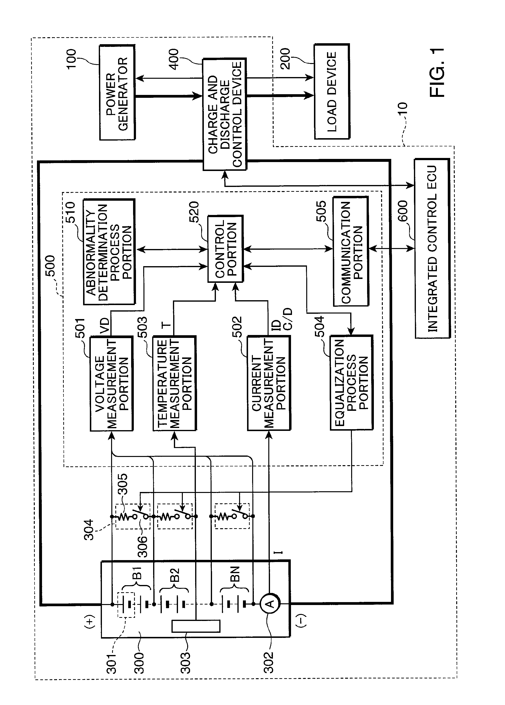
[0035]FIG. 1 is a view showing the configuration of a power supply system equipped with an abnormality detecting device according to a first embodiment of the invention. Referring to FIG. 1, a power supply system 10 according to the first embodiment of the invention includes a power generator 100 that generates electric power from natural energy, such as sunlight, wind power, and hydraulic power, a storage device 300 that stores surplus electric power from the power generator 100 and feeds the stored electric power as needed to a load device 200 driven by a supply of electric power, a charge and discharge control device 400 that controls charge and discharge of the storage device 300, an abnormality detecting device 500 that performs an abnormality detection process on the storage device 300, and an integrated control ECU (Electric Control Unit) 600 that is connected to both the abnormality detecting device 500 and the charge and discharge control device 400 and controls the overall...

second embodiment

[0077]A second embodiment of the invention will now be described. The abnormality detecting method of the first embodiment above is to perform an abnormality determination using the voltages across the terminals of the respective storage element blocks when a predetermined time has elapsed since the end of the equalization process in the abnormality determination process of FIG. 5. By contrast, an abnormality detecting method of this embodiment is to perform the abnormality determination process using a difference of the voltages across the terminals of different storage element blocks when a predetermined time has elapsed. By using this difference, it becomes possible to improve accuracy of the abnormality determination further than in the first embodiment above.

[0078]The abnormality detecting method according to the second embodiment of the invention will be described in the following. The equalization process by the abnormality detecting method of this embodiment is the same as t...

third embodiment

[0086]A third embodiment of the invention will now be described. According to the abnormality detecting methods of the first and second embodiments above, the voltages across the terminals of the respective storage element blocks and differences in voltages across the terminals are calculated after an elapse of the predetermined time since the base point set at the end of the equalization process on all the storage element blocks B1, B2, . . . , and BN in the abnormality determination processes in FIG. 5 and FIG. 6. By contrast, an abnormality detecting method of this embodiment is to perform the abnormality determination process using a voltage across the terminals after an elapse of a predetermined time since the end of the equalization process on each storage element block.

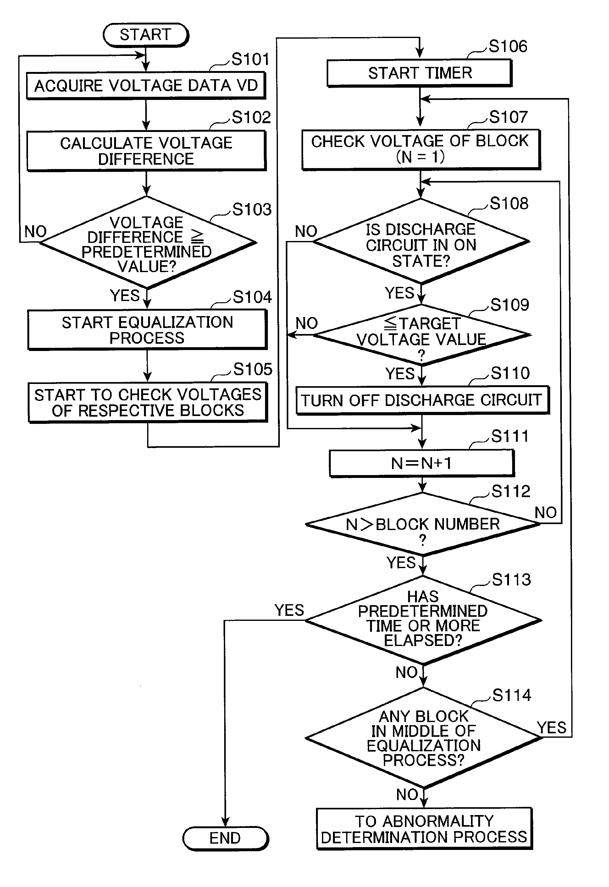
[0087]An abnormality detecting method for the storage elements according to the third embodiment of the invention will be described in the following. FIG. 7 is a flowchart depicting the procedure of the equaliz...


PUM

PropertyMeasurementUnit
states of chargeaaaaaaaaaa
voltageaaaaaaaaaa
voltagesaaaaaaaaaa

Abstract

An abnormality detecting device for a storage element is able to improve accuracy of abnormality detection for the storage element. The device includes at least an equalization process portion, an abnormality determination portion, a voltage measurement portion, and a control portion. The control portion issues a command to the equalization process portion to start an equalization process in a case where there is a variance in capacity of storage element blocks B1, B2, . . . and BN. The abnormality determination portion performs an abnormality determination on the storage element blocks B1, B2, . . . , and BN using voltages across the terminals of the respective storage element blocks B1, B2, . . . , and BN that have been allowed to stand after an elapse of a predetermined time since the end of the equalization process.

Description

RELATED APPLICATIONS[0001]This application is the U.S. National Phase under 35 U.S.C. §371 of International Application No. PCT / JP2007 / 071338, filed on Nov. 1, 2007, which in turn claims the benefit of Japanese Application No. 2006-299364, filed on Nov. 2, 2006, the disclosures of which Applications are incorporated by reference herein.TECHNICAL FIELD[0002]The present invention relates to an abnormality detecting device for a storage element capable of improving accuracy of abnormality detection on a storage element incorporated into a power supply system, an abnormality detecting method for a storage element, an abnormality detecting program for a storage element, and a computer-readable recording medium for storing an abnormality detecting program.BACKGROUND ART[0003]Recently, a storage device is combined with a power generator, for example, a solar cell, so as to be used as a power supply system. The power generator generates electric power using natural energy, such as sunlight,...

Claims


Application Information

Patent Timeline
Patent Type & Authority Patents(United States)
IPC IPC(8): G01N27/416H02J7/00H02J7/02
CPCH02J7/0021H01M10/48H01M10/44Y02T10/7055Y02T10/70Y02E60/10H02J7/0048H02J7/005H02J7/0016
Inventor IIDA, TAKUMA
Owner PANASONIC CORP
Why Eureka
Try Eureka