Power supply apparatus

a power supply apparatus and power supply technology, applied in the direction of power conversion systems, dc-dc conversion, dc source parallel operation, etc., can solve the problems of limiting output power, damage to the power supply apparatus and a circuit connected, and the smps does not properly control the continued abnormal curren

Inactive Publication Date: 2011-12-27
S PRINTING SOLUTION CO LTD
View PDF3 Cites 1 Cited by
  • Summary
  • Abstract
  • Description
  • Claims
  • Application Information

AI Technical Summary

Benefits of technology

[0017]According to another aspect of the present invention, the current transformer reduces the current of the primary winding corresponding to the turns ratio and induces the current to the secondary winding.

Problems solved by technology

Over current protection (OCP) and over voltage protection (OVP) systems can limit the output power.
In some cases, however, the output voltage or the output current may remain between the reference value at which the switching operation is suspended and a normal value (the SMPS may operate in an abnormal state).
Under this circumstance, if the output power is not properly limited, a continued over voltage or over current may damage the power supply apparatus and a circuit connected to an output terminal of the power supply apparatus.
However, the conventional SMPS does not properly control the continued abnormal current while limiting the output power if the abnormal voltage is continuously applied.
A circuit can be damaged if the over current is continuously applied for a long time.

Method used


Image

  • Power supply apparatus
  • Power supply apparatus
  • Power supply apparatus

Examples


Embodiment Construction

[0024]Reference will now be made in detail to the present embodiments of the present invention, examples of which are illustrated in the accompanying drawings, wherein like reference numerals refer to the like elements throughout. The embodiments are described below in order to explain the present invention by referring to the figures.

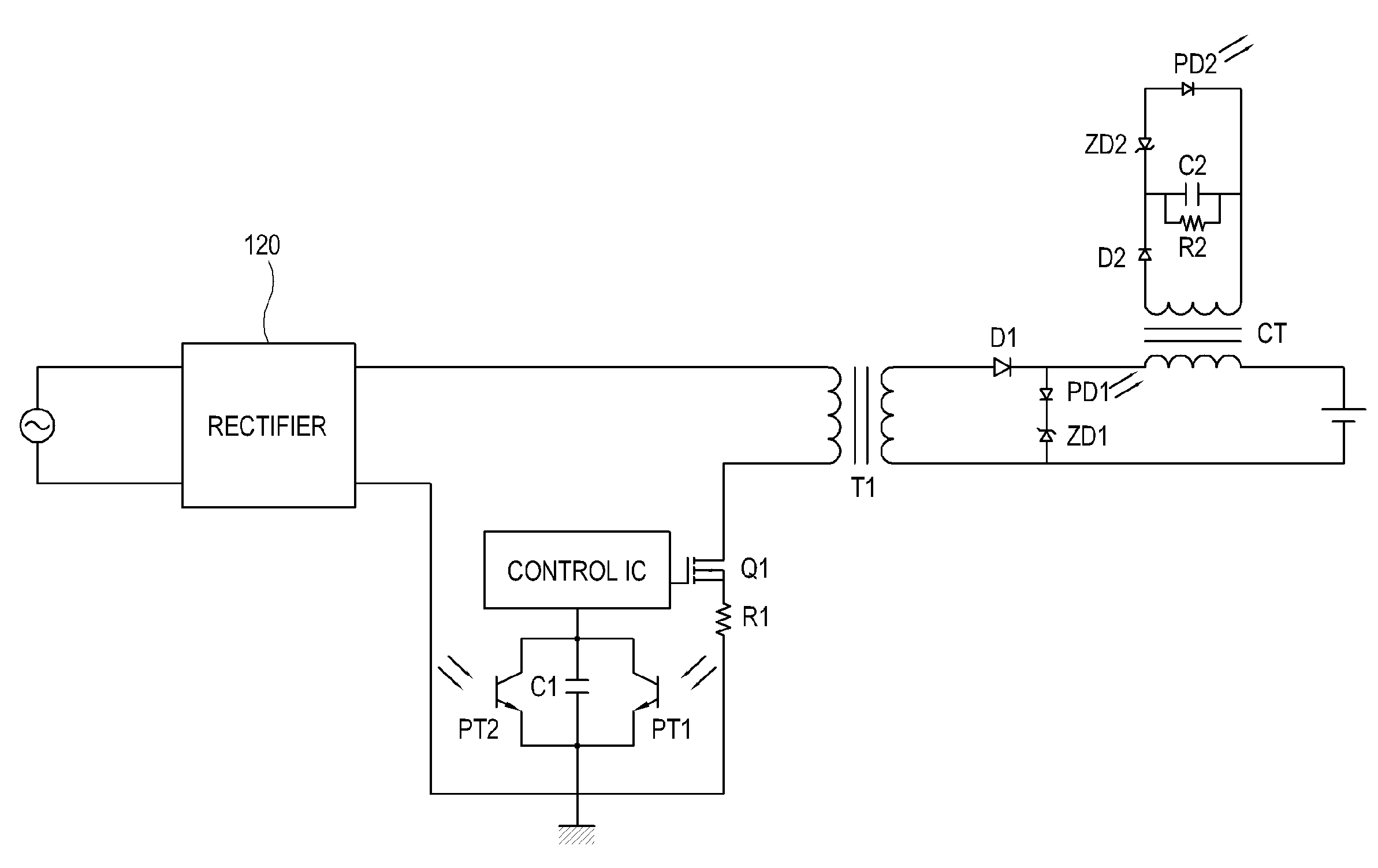
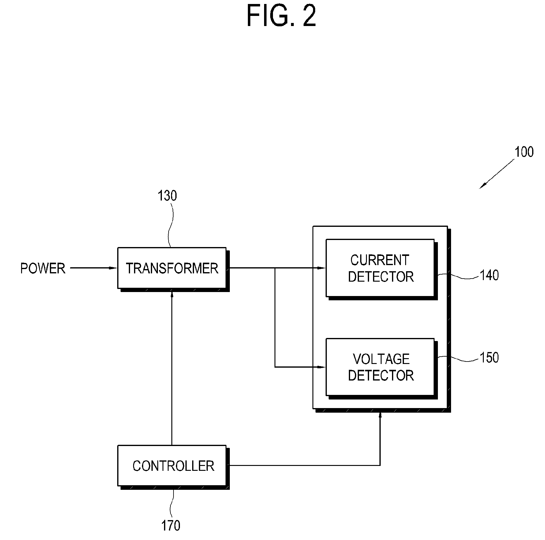
[0025]FIGS. 2 and 3 show a power supply apparatus 100 according to an embodiment of the present invention. The power supply apparatus 100 includes a power supply unit 110, a rectifier 120, a transformer 130, a current detector 140, a voltage detector 150, a switch 160, and a controller 170. According to other aspects of the present invention, the power supply apparatus 100 may include additional and / or other units. Similarly, the functionality of two or more of the above units may be integrated into a single component.

[0026]The power supply unit 110 receives AC (alternating current) power from an outside source. The rectifier 120 rectifies the AC power...


PUM


Abstract

A power supply apparatus includes: a transformer which converts input power supplied to a primary winding to be induced to a secondary winding; a current detector which detects an output current of the secondary winding of the transformer; a voltage detector which detects an output voltage of the secondary winding of the transformer; a switch which adjusts the output voltage outputted by the transformer; and a controller which controls the switch to maintain output power obtained by multiplying the output current by output voltage, within a predetermined level.

Description

CROSS-REFERENCE TO RELATED APPLICATION[0001]This application claims the benefit of Korean Application No. 2007-84069, filed in the Korean Intellectual Property Office on Aug. 21, 2007, the disclosure of which is incorporated herein by reference.BACKGROUND OF THE INVENTION[0002]1. Field of the Invention[0003]Aspects of the present invention relate to a power supply apparatus, and more particularly, to a switching mode power supply (SMPS) that prevents damage due to an over voltage or an over current.[0004]2. Description of the Related Art[0005]Generally, a switching mode power supply (SMPS) rectifies AC (alternating current) power inputted from the outside, to be supplied to elements of an electronic device. The SMPS is widely employed in electronic devices, such as a printer.[0006]FIG. 1 is a circuit diagram of a conventional switching mode power supply (SMPS). The conventional SMPS includes a transformer T1, a photocoupler light emitter PD1 and a photocoupler light receiver PT1, a ...

Claims


Application Information

Patent Timeline
Patent Type & Authority Patents(United States)
IPC IPC(8): H02M3/335
CPCH02M3/33553H02M3/28
Inventor LEE, SEUNG-HAK
Owner S PRINTING SOLUTION CO LTD
Why Eureka
Try Eureka