Glass forming apparatus and method

a technology of glass forming and glass forming, which is applied in the direction of glass tempering apparatus, glass rolling apparatus, manufacturing tools, etc., can solve the problem of insufficient heat absorption and other problems, and achieve the effect of high quality and efficien

Inactive Publication Date: 2012-01-03
OHARA
View PDF17 Cites 1 Cited by
  • Summary
  • Abstract
  • Description
  • Claims
  • Application Information

AI Technical Summary

Benefits of technology

[0014]According to the first aspect of the invention, as the die is constructed such that the wall thickness of the solid press surface decreases gradually or stepwisely from the outside to the inner side thereof, for example, when the opposite press surface absorbs heat transmitted from the press surface for pressing glass generally on the center of the press surface and the absorbed heat is heat-exchanged with the outside, the center of the opposite press surface, where most of heat is desired to be absorbed, is allowed to absorb the most of heat. On the other hand, the end of the opposite press surface, where the heat is absorbed insufficiently compared with that of the center of the press surface. Therefore, the whole press surface is retained at favorable temperatures for pressing glass, so that a high-quality, efficient glass form can be formed. In the case of a convex lens, even though there is a conventional example formed such that the die becomes thinner from the outside to the inside depending on the shape of a press surface, the present invention causes variations in wall thickness of a die depending on the shape of at least an opposite press surface, thereby being clearly distinguished from the conventional one.
[0034]According to the present invention, the die is constructed such that the wall thickness of an opposite press surface decreases gradually or stepwisely from the outside to the inner side thereof. For example, when the opposite press surface absorbs heat transmitted from the press surface for pressing glass, which can be generally mounted on the center of the press surface, to take the heat from the press surface by heat exchange of the absorbed heat with the outside, the heat can be mostly absorbed at the center of the opposite press surface being most in need of heat absorption, while the heat can be moderately absorbed at the end of the opposite press surface being less in need of heat absorption than the center. Therefore, the whole press surface is retained at favorable temperatures for pressing glass, so that a high-quality, efficient glass form can be formed.

Problems solved by technology

On the other hand, the end of the opposite press surface, where the heat is absorbed insufficiently compared with that of the center of the press surface.

Method used


Image

  • Glass forming apparatus and method
  • Glass forming apparatus and method
  • Glass forming apparatus and method

Examples


second embodiment

[0073]Next, a preferable second embodiment of the present invention will be described with reference to the drawings.

[0074]Here, in the following embodiment, the same structural elements as those of the first embodiment will be given the same reference numerals and the descriptions thereof may be omitted or simplified.

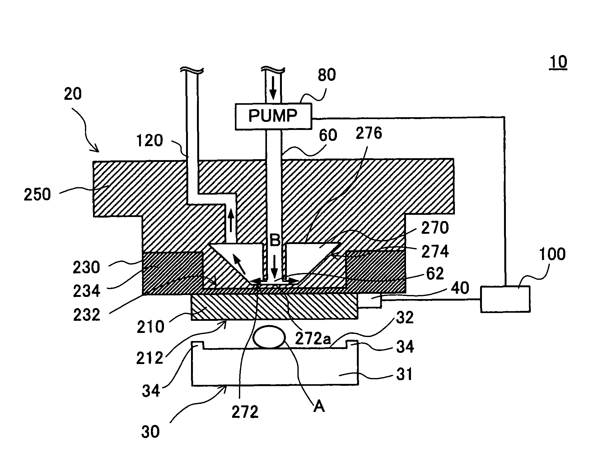
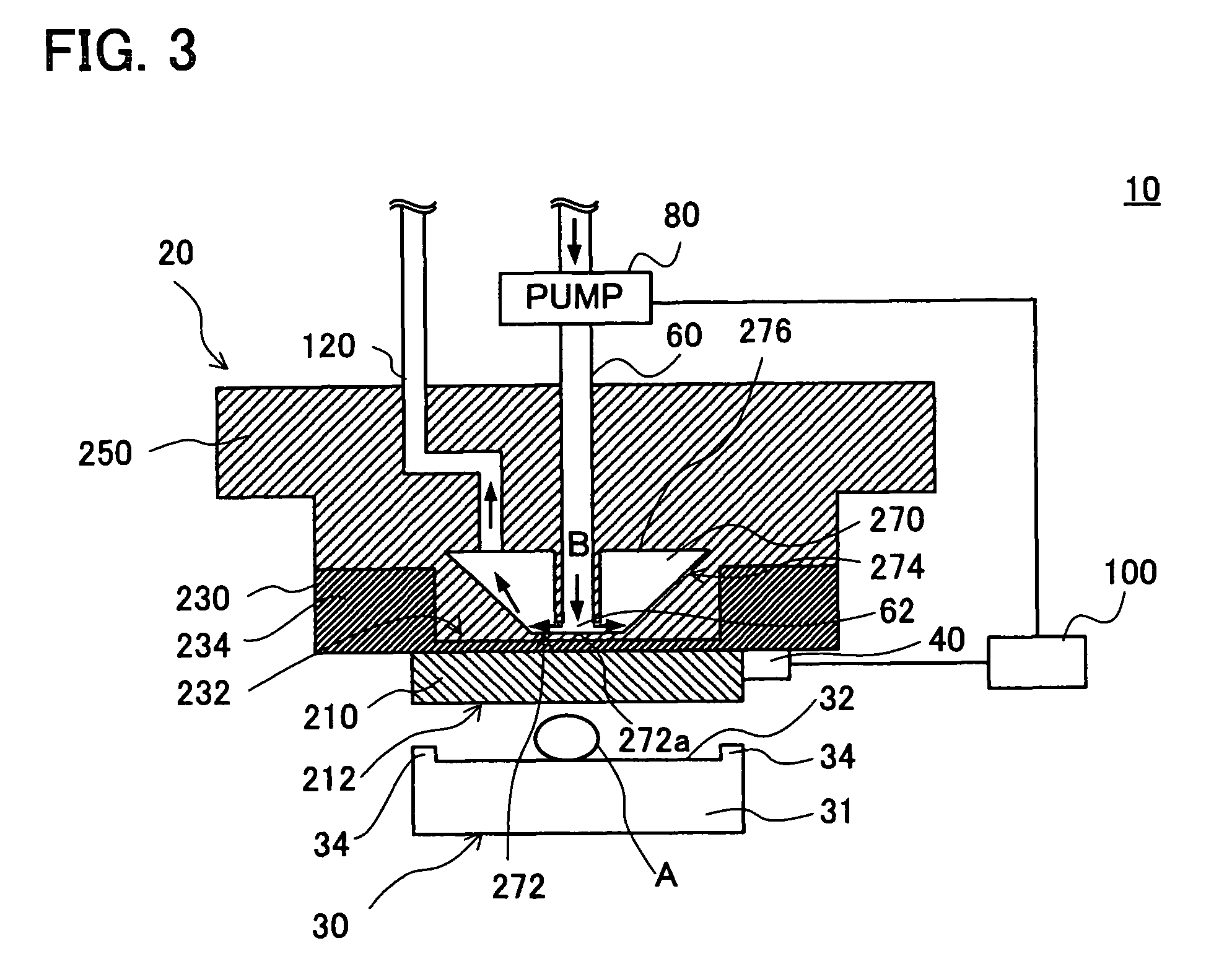
[0075]FIG. 5 shows a preferable example of the second embodiment of the present invention, and a partial cross sectional front view of the schematic configuration of a glass forming apparatus. The configuration of a glass forming apparatus 310 of the second embodiment is different from that of the glass forming apparatus 10 of the first embodiment in that an upper die 20 of the glass forming apparatus 310 is constructed such that the wall thickness of an opposite press surface decreases from the outside to the inside in a plural stepwise manner.

third embodiment

[0076]Next, a preferable third embodiment of the present invention will be described with reference to the drawings.

[0077]FIG. 6 shows a preferable example of the third embodiment of the present invention, and a partial cross sectional front view of the schematic configuration of a glass forming apparatus. The configuration of a glass forming apparatus 410 of the third embodiment is different from that of the glass forming apparatus 10 of the first embodiment in that the glass forming apparatus does not contain a third upper die 250 (in which a heat exchange chamber 250 is formed), a temperature sensor 40, a tube 60 for introducing a heat-exchanging fluid, a pump 80, a control circuit 100, and a tube 120 for discharging a heat-exchanging fluid, and also a protruded part 234 provided as an example of the opposite press surface of the second upper die 230 is constructed such that the wall thickness of the protruded part 234 gradually decreases from the outside to the inside. In the pr...


PUM

PropertyMeasurementUnit
thicknessaaaaaaaaaa
diameteraaaaaaaaaa
temperatureaaaaaaaaaa

Abstract

A glass forming apparatus and a glass forming method are provided, which are capable of retaining the whole press surface at favorable temperatures for pressing glass, and forming a high-quality, efficient glass form. An upper die having a part formed such that the wall thickness of a bottom part, provided as an example of an opposite press surface, decreases gradually from the outside to the inside and the bottom part is formed as a part of the inner wall. In other words, the heat exchange chamber is in approximately a circular truncated cone shape.

Description

[0001]This application is based on and claims the benefit of priority from Japanese Patent Application No. 2005-300765, filed on 14th Oct. 2005, the content of which is incorporated herein by reference.BACKGROUND OF THE INVENTION[0002]The present invention relates to a glass forming apparatus and a glass forming method, and in particular, relates to an apparatus and method for forming a glass substrate or a crystallized glass substrate, which can be used for preparing a disk for an information storage medium.Related Art[0003]An optical device, such as a lens, a glass substrate for a disk of an information storage medium, or the like is generally produced so that a glass mass (molten glass) can be pressed into shape by any of methods including a direct press method and a repeated press method.[0004]The direct press method presses a glass mass into a predetermined shape using a die (which is a forming die having an upper die part and a lower die part) after lowering a predetermined-we...

Claims


Application Information

Patent Timeline
Patent Type & Authority Patents(United States)
IPC IPC(8): C03B11/12
CPCC03B11/122C03B11/125
Inventor NOZAKI, MORIJI
Owner OHARA
Why Eureka
Try Eureka