Display

a technology of display and display panel, applied in the field of display panel, can solve the problems of low light efficiency, optical crosstalk problem, objectable visible motion artifact, etc., and achieve the effect of overcoming

Active Publication Date: 2012-01-03
PAKHCHYAN EDWARD
View PDF10 Cites 6 Cited by
  • Summary
  • Abstract
  • Description
  • Claims
  • Application Information

AI Technical Summary

Benefits of technology

[0007]It is an object of the present invention to provide a display that effectively overcomes the optical crosstalk problem typically found in prior art optical waveguide-based displays while displaying the entire image simultaneously. In one form of the invention this object is achieved by providing a display that comprises a light source and an optical waveguide. The optical waveguide distributes light to a plurality of light exits. At each light exit a picture element modulates light by selectively directing the light to the viewer or to a light absorber.
[0008]Another object of the invention is to provide a high contrast display of the character that operates at high levels of ambient light. Two embodiments of the invention achieve this object by providing a display wherein the majority of the viewing surface is coated with a light-absorbing coating. In the third embodiment of the invention this object is achieved by providing a display which includes a prism film at the upper surface of the display. In this latter embodiment, the prism film redirects light emitting from the display at oblique angles towards the normal so as to improve the viewing angles. The same prism film absorbs most of the ambient light when a light-absorbing coating is applied on the same facets that redirect the display light.
[0009]Another object of the invention is to provide a display that can compete with LCD's in light efficiency, picture quality and cost. Increased light efficiency is achieved by providing a display in which light travels most of the light path by total internal reflections and light is modulated by requiring fewer reflections from highly reflective micro-mirrors. Improved picture quality is achieved by providing fast and efficient light modulators.

Problems solved by technology

A further problem with LCDs is the slow response time of the liquid crystal resulting in objectionable visible motion artifacts when displaying motion images.
There is an inherent optical crosstalk problem when picture elements are simultaneously activated to display an image.
This requires very fast micro-mechanical actuators and results in very low light efficiency.
Displaying color or grey scale images is generally not practical.
Another common problem concerns the use of mirror surfaces to redirect light to the viewer.

Method used


Image

  • Display
  • Display
  • Display

Examples


Embodiment Construction

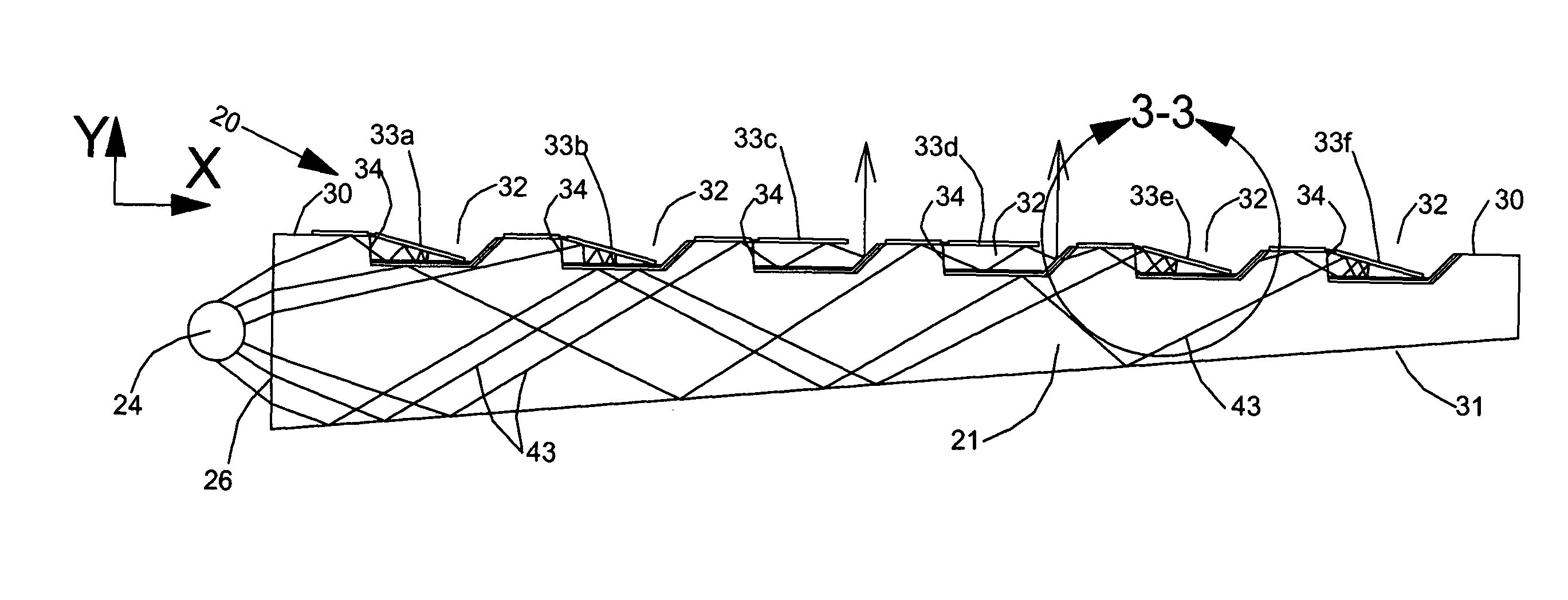
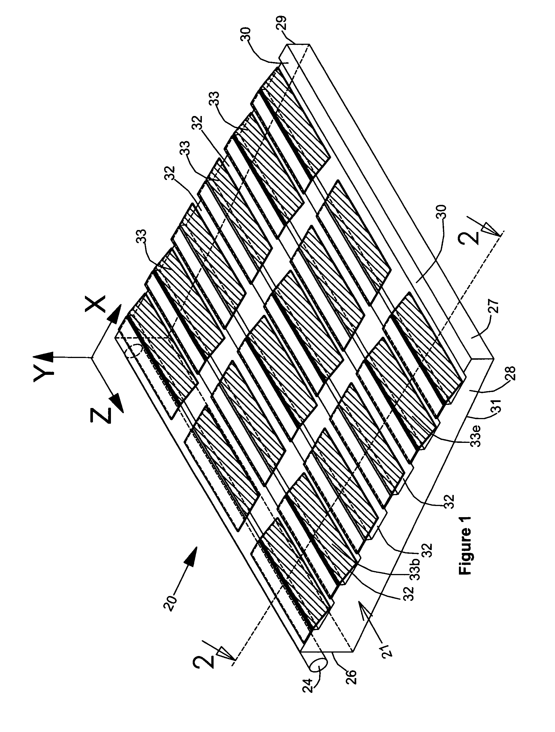
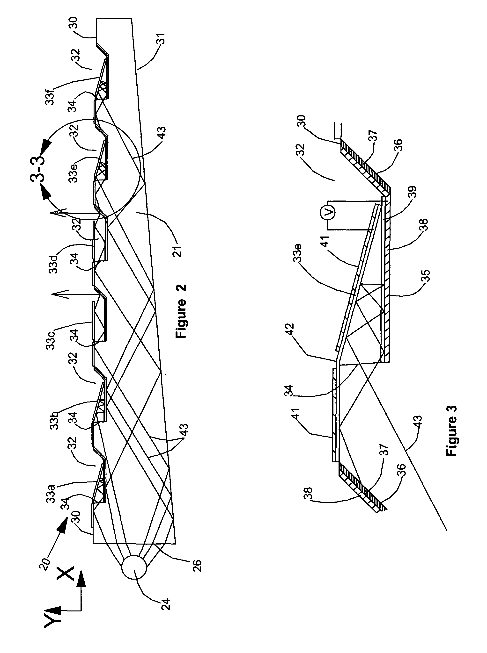
[0022]Referring to the drawings and particularly to FIGS. 1 and 2, one form of the display of the invention is shown there and generally designated by the numeral 20. As best seen in FIG. 1, display 20 here includes a generally rectangular shaped optical waveguide 21 that is a substantially wedge-shaped cross section. Waveguide 21 is preferably constructed from an optically transparent material, such as acrylic or glass and comprises generally parallel first and second end surfaces 26 and 27 that are joined by parallel side surfaces 28 and 29 (see FIG. 1). Waveguide 21 also includes a specially configured major upper surface 30 and an upwardly inclined lower surface 31 (see also FIG. 2). A plurality of substantially equally spaced-apart grooves 32 are formed on upper surface 30 and, as shown in FIG. 1, extend between side surfaces 28 and 29. An elongated light source 24 is installed proximate the wide edge 26 of the waveguide 21 and a novel matrix of tilting micro-mirrors 33 is cons...


PUM


Abstract

A display including a light source for generating light, an optical waveguide for receiving and evenly distributing light in a light propagation direction by total internal reflections and a matrix of picture elements constructed on the upper surface of the waveguide, the picture elements including electrically activated micro-mechanical actuators having optical properties for modulating light to produce an image.

Description

BACKGROUND OF THE INVENTION[0001]1. Field of the Invention[0002]The present invention relates generally to displays. More particularly the invention concerns displays comprising an optical waveguide, a light source and a plurality of electrically activated micro-mechanical actuators with optical properties.[0003]2. Discussion of the Prior Art[0004]Currently liquid crystal displays dominate the flat panel display market. Prior art liquid crystal displays typically comprise a backlight assembly for illumination, light polarizers, color and neutral density filters, and an active matrix liquid crystal layer with thin-film-transistor backplanes. The overall light efficiency of a typical prior art liquid crystal display (LCD) is below 10% mainly due to the fact that light from the backlight assembly has to pass several layers of polarizers, color and neutral density filters. A further problem with LCDs is the slow response time of the liquid crystal resulting in objectionable visible moti...

Claims


Application Information

Patent Timeline
Patent Type & Authority Patents(United States)
IPC IPC(8): F21V7/04
CPCG02B6/0033G02B26/0841G02B6/0038G02B6/0053
Inventor PAKHCHYAN, EDWARDMESROPIAN, HAIKPAKHCHYAN, SYUZI
Owner PAKHCHYAN EDWARD
Why Eureka
Try Eureka