Piezoelectric loudspeaker

a piezoelectric speaker and loudspeaker technology, applied in the field of piezoelectric loudspeakers, can solve the problems of poor sound quality of piezoelectric speakers driven within their break-up regions, speaker peaks or dips are more prone to frequency response peak or dip, and the overall sound output of piezoelectric speakers is typically limited. , to achieve the effect of reducing the acoustic properties of the system, good results, and high overall sound outpu

Inactive Publication Date: 2012-01-03
VIBRATION X
View PDF9 Cites 8 Cited by
  • Summary
  • Abstract
  • Description
  • Claims
  • Application Information

AI Technical Summary

Benefits of technology

[0022]The fabric membrane attached to the frame is doped with a filler material such as epoxy resin or paint for stiffening the fabric material.
[0025]According to a preferred embodiment, the material can be further doped and coated (brush or spray painting) to obtain a finished look and good audio performance.
[0028]This method will not only allow for an integrated design, but it will also provide great flexibility in the frequency ranges to be covered.
[0032]the membrane material is water resistant and temperature resistant, making the overall device feasible for both automotive and outdoors applications;
[0035]piezoelectric speaker provide greater “ambient” and “spacious” sound due to the complex radiation patterns created by actuating higher order modes;

Problems solved by technology

Conventional wisdom says that speakers driven within their break up region have poor quality sound because the resulting resonances create audible peaks and dips in the frequency response.
These speakers also are more prone to peaks or dips in the frequency response in the crossover region where two transducers may be operating at the same output level.
The sound quality of a piezoelectric speaker is typically limited by the shape and size of the structure to which the piezoelectric material is attached.
For this reason, prior use of piezoelectric materials used to generate audio sounds has been limited to single frequency audio sounds generators such as buzzers or alarm devices.
There have been attempts to use a piezoelectric actuator driving an amplifying structure as a full range audio speaker, but the size and rigidity of the structure have made it difficult to obtain an acceptable low frequency sound response.
The complex surface displacement of the driven amplifying structure, resulting from the superposition of several vibrational modes at a given frequency, causes an air pressure wave to radiate away from the structure in very complex, multi-beam patterns.

Method used


Image

  • Piezoelectric loudspeaker
  • Piezoelectric loudspeaker
  • Piezoelectric loudspeaker

Examples


Embodiment Construction

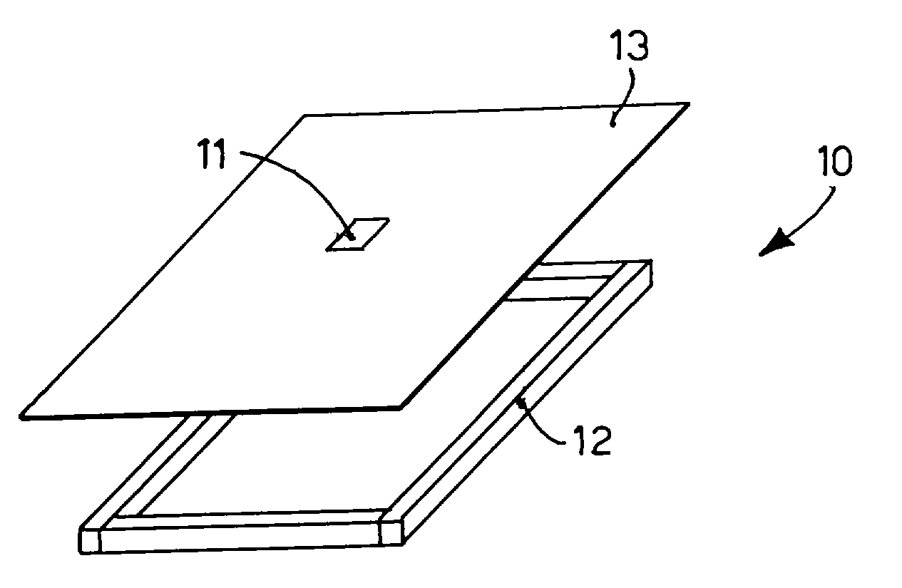
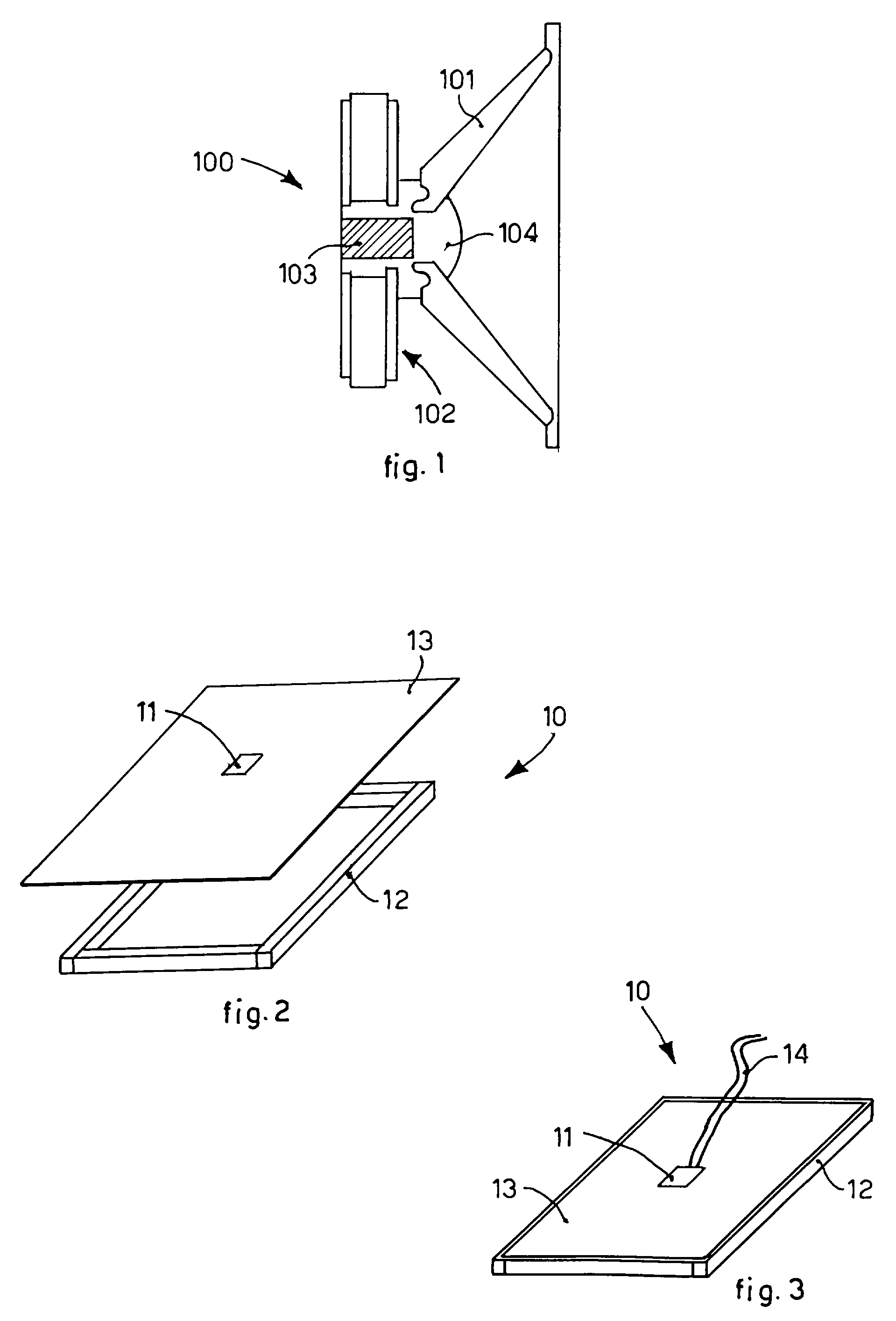
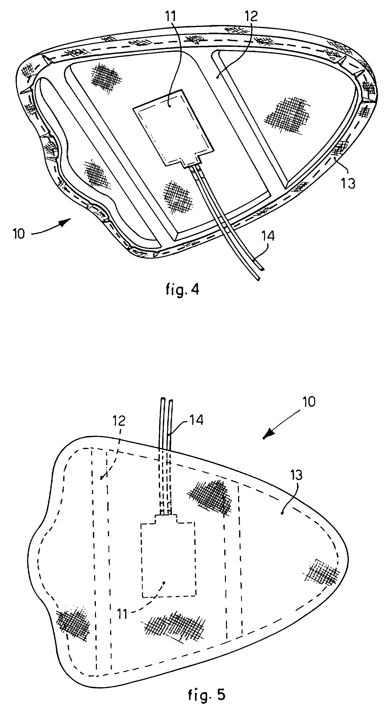
[0056]The piezoelectric loudspeaker 10 according to the invention is shown in a form of embodiment in FIGS. 4 and 5.

[0057]In this form of embodiment, the loudspeaker 10 includes a single small piezoelectric actuator 11, but it is clear that it could as well include a multiplicity of piezoelectric actuators distributed on the surface of the panel. The number and the distribution of the piezoelectric actuators 11 on the surface of the loudspeaker 10 may be designed according to the specific application and the audio performance to be obtained.

[0058]The loudspeaker 10 comprises, as its essential components, a thin frame 12 (see step 20 in the block diagram of FIG. 6) which can have a suitable shape according to the needed requirements for the installation. In addition, the frame member may comprise any opening formed in a solid structure that the fabric membrane can be stretched across. One example is an opening formed in an automobile dashboard or door panel. Another example is an ope...


PUM

PropertyMeasurementUnit
frequencyaaaaaaaaaa
frequencyaaaaaaaaaa
resonant frequencyaaaaaaaaaa

Abstract

A full range loudspeaker, comprising a frame with a membrane secured onto said frame and a piezoelectric actuator attached on said membrane and able to be driven over the full audible frequency range.

Description

[0001]This application is a §371 national phase filing of PCT / EP2007 / 053286 filed Apr. 4, 2007, and claims priority benefit of U.S. Provisional application No. 60 / 790,258 filed Apr. 7, 2006.[0002]The present invention refers to a piezoelectric loudspeaker, and to a method to design and make a full range piezoelectric loudspeaker.[0003]More particularly, the piezoelectric loudspeaker according to the invention has an improved low frequency response, and is able to be driven at a wide range of audio signal frequencies, e.g. from about 5 Hz up to 100 KHz.STATE OF THE ART[0004]Piezoelectric loudspeakers have been used in audio systems to generate high frequency audio sound (tweeters, ultrasonic sound generators, etc.), but they have never been used to cover the low frequency range, which is typically covered by a conventional voice coil speaker.[0005]Sound system designers historically have used electromagnetic “voice coil” transducers to generate air displacement.[0006]FIG. 1 discloses...

Claims


Application Information

Patent Timeline
Patent Type & Authority Patents(United States)
IPC IPC(8): H01L41/08
CPCH04R17/00Y10T29/49005
Inventor BIANCHINI, EMANUELE
Owner VIBRATION X
Why Eureka
Try Eureka